3M 710 Anleitung Handbuch - Seite 10
Blättern Sie online oder laden Sie pdf Anleitung Handbuch für Projektor 3M 710 herunter. 3M 710 20 Seiten. Splicing rig
Auch für 3M 710: Broschüre & Specs (4 seiten), Spezifikationen (4 seiten)

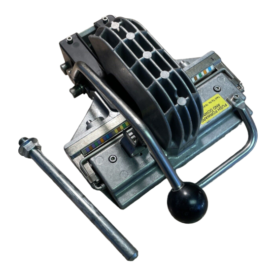
4.5 Spread the conductors around the "T" bar without
disturbing them in the module body. Pull the "T" bar
up above the module body. Push the "T" bar forward
and down until contact is made with the conductors.
Pull the handle down to the stop, seating and cutting
the conductors in the module body. Remove the
excess conductors. Engage the handle into the
retaining clip, pull the "T" bar up, and place into the
open position.
4.6 Place a cap on the module body. Use finger pressure
to push down the cap to pre-engage it to the module
body. The cap latches should face the color code
guide. Pull the "T" bar up above the cap. Push the
"T" bar forward and down until contact is made with
the cap. Pull the handle down to the stop, seating the
cap into the module body. Engage the handle into
the retaining clip, pull the "T" bar up, and place into
the open position. Push in the "L" clip to release the
module and remove from the splicing rig. The 25-
pair half-tap splice module is complete.
5.0 Bridge Splicing with 3M
Module Support
5.1 Place a red bridge module support into the splicing
rig with the word FRONT facing the color code
guide. Push the "L" clip in to secure the bridge
module support.
5.2 Place a bridge module into the bridge module
support with the cathedral windows facing the color
code guide.
710 25-pair Modules using the Red Bridge
™
10
78-815-304--E
