Fleischmann 9152 C Betriebsanleitung - Seite 4
Blättern Sie online oder laden Sie pdf Betriebsanleitung für Spielzeug Fleischmann 9152 C herunter. Fleischmann 9152 C 6 Seiten.
Ölen des Motors
Fig. 13
Um die Lager des Antriebsmotors ölen zu können,
muss die Gitterabdeckung vor dem Wärterhaus mit einem klei-
nen Schraubendreher abgehoben werden.
Ausbau der Drehbühne
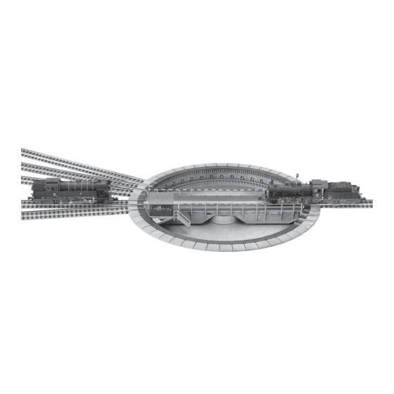
TURNTABLE 9152C (Fig.1).
The FLEISCHMANN turntable 9152C was constructed as a built-in turntable for the N«piccolo» track system. Complete with trench and turning platform this is a true-to-life
model. The turntable is electrically operated and can be operated remotely by the turntable switch 6910, which is included. The switch will fit into the FLEISCHMANN dia-
grammatic control. Installation (Fig. 2): For installing the turntable you will need a hole with 205 mm diameter in your layout board. It will not be necessary to fasten it
down, as the turntable will be stopped at fastened tracks. If the turntable has to be laid on top of the layout, a base of polystyrene (or similar) should be laid underneath. In
this case entry and exit ramps 25 mm high must be creat ed for the tracks. The turntable is divided into 7.5° sections with a maximum of 48 possible rail connections. The
7.5° sections are provided to match up to the standing positions of 3 locos in the loco shed 9575. For each loco stand, 1 x 9100 and 1 x 9101 tracks will be required. Con-
necting the motor of the platform (Fig. 3): Attention! First connect all of the wires of the turntable and its switch before you connect the mains transformer to the
AC-outlet. Otherwise you risk the damage of the switch caused by short-circuit. The 3 wires, red, yellow and grey must be connected to the corresponding wires on the
switch, if necessary with the 6941 connector. The black and white wire from the switch must go to the A.C. connection on the transformer/controller (type 670601, 6725,
6735, 6755) – also for digital operation. Rotating the turntable by hand, see Figs. 11 and 12. Connecting current to the platform: The twin yellow wires of the turntable
should be connected to the clips for the D.C. on the transformer/controller. If operating the layout digitally, then the twin yellow wires should not be connected to the trans-
former, but connected to the lilac and lilac/white of the digital controller. Controlling the connecting track (Fig. 4): With this turntable switch the platform can be turned
either to the left or right by means of the black switch. The platform stops automatically at each track. A continuous action through to your chosen position is possible if the
switch is pushed into the direction of travel to its outer limit until the position is reached. On reaching this position, it is stopped by pressing in the opposite direction. Feed-
ing the connecting track with power (Figs 5/6): In conjunction with the turntable switch 6910, each connecting track of this "thinking" turntable can be selected to be
fed with power from the turntable bridge. If the turntable switch 6910 is turned to the position marked " ", then the connecting track which is lined up with the turntable
bridge side with the attendant's cab will be fed with power. If the turntable switch is turned to the position marked " ", then the connecting track which is lined up with
the turntable bridge side without the attendant's cab will be fed with power. With this "comfort" turntable, then either one or the other track will be fed with power, and
never both at the same time. In this way, a loco can be stored on a track without power, an simultaneously, one located on the track lined up immediately opposite the turn-
table bridge can still be operated. Operation of the layout with two or more transformers/controllers (Fig. 7): The turntable area should be controlled by a separate
transformer/controller. All lines which go over into the turntable area should be cut off with two isolating fish plates. Operation of the layout with one transformer/con-
troller (Fig. 8): It is possible to operate the whole layout with just one transformer. As before all lines to the turntable area are cut off with two isolating fish plates. Current
is fed into the line. The turntable is also fitted with a switch 6904/6924 or a pause switch 6905. Extension (Fig. 9): With the Extension Set 9153 the turntable can be ex-
tended to cope with three rail connections. The turntable should be placed away from the area of the installed parts. The cover plates are now pulled up by pushing back the
spring switch-tongues (Fig.10), and stuck in the approach track. Every approach track is to be set up opposite a blind section or another approach track. Rotating the turn-
table by hand (Fig. 11): Opposite the motor housing, under the turning table, is a small black lever. By pressing the lever towards the centre, the drive gear wheel is with-
drawn from the teeth in the outer drive ring releasing the table so that it can be moved manually in the desired direction. When the lever is released the gear wheel is again
enmeshed with the outer-ring. Ensure, however, that the rotating tracks are lined up with the exit tracks. Should the turntable not operate, when pressing the switch 6910,
simply press the lever slightly to ensure the gear wheel is firmly seated in the drive ring, which will then start it moving. It will then stop at the next track again (Fig. 12).
Oiling the motor (Fig. 13): To oil the drive motor both lattice cover plates must be removed from the machine house with a screwdriver. Just one drop of oil should be put
through the holes to lubricate the points as shown (Fig. 14). Only use FLEISCHMANN-oil 6599. An applicator needle is located in the cap of the oil bottle for your use. Dis-
mantling the table (Fig. 15): Should the turntable not operate by moving the lever, it will be necessary to dismantle the table. Using a small screwdriver, gently lift the
small coverplate in the centre of the table between the two rails and spring off the circlip on the central pivot. Be careful not to lose the circlip! On each side of the platform
take off 6 opposing components (Fig. 10). Now the platform can be removed. The contact points and springs round the central pivot should be cleaned. To put the table back
together simply reverse the procedure. In the unfortunate instance that the turntable should still not function, please return it to your local dealer or to your supplier or direct
to the FLEISCHMANN Technical Centre.
21-9152-0102.indd 6
21-9152-0102.indd 6
Fig. 14 Durch die vorgesehenen Löcher ist je 1 Tropfen Öl an
die durch Pfeile gekennzeichneten Lagerstellen zu geben. Vor-
sicht, nicht überölen! Nur FLEISCHMANN-Öl 6599 verwenden.
Zur Dosierung die in der Verschlusskappe der Ölflasche ange-
brachte Nadel verwenden.
Fig. 15 Läuft die Drehbühne auch nach Betätigung des Handhebels nicht an,
muss sie ausgebaut werden. Dazu wird mit einem kleinen Schraubendreher die
mittlere Gitterabdeckung zwischen den Schienen der Bühne abgehoben und der
Sicherungsring am Drehzapfen entfernt. Vorsicht! Sicherungsring nicht verlie-
ren! Auf jeder Seite der Drehscheibe werden mindestens 6 gegenüberliegende
Teilstücke entfernt (siehe Fig. 10). Jetzt kann die Bühne in diesen Ausschnitt ge-
fahren und herausgehoben werden.
Die Kontaktbahnen neben dem Drehzapfen und die Kontaktfedern sind zu reinigen.
Der Einbau der Bühne erfolgt in umgekehrter Reihenfolge.
Gegebenenfalls ist bei schadhaften Teilen die Drehbühne mit Schalter 6910 an
die Kundendienstabteilung einzusenden.
Änderungen, Liefermöglichkeiten und alle Rechte vorbehalten.
Daten, Maßangaben und Abbildungen ohne Gewähr.
We reserve all rights to carry out alterations and improvements of all models or items.
13.01.2022 08:27:03
13.01.2022 08:27:03