Dogtra E-Fence 3500 Benutzerhandbuch - Seite 9
Blättern Sie online oder laden Sie pdf Benutzerhandbuch für Kontrollsysteme Dogtra E-Fence 3500 herunter. Dogtra E-Fence 3500 16 Seiten.

Testing Your Dogtra E-Fence 3500 Prior
to Installation
2. Unwind the length of ground wire that was provided and strip
about 1/2 inch off each end. Insert both ends of the ground wire
into the outer, red wire connector jacks, leaving the center jack
free. If the wires are connected properly, the wire indicator light
will be on.
3. Next, activate the receiver/collar by turning the intensity level
dial on the receiver to the desired level. The LED light will
blink once every two seconds showing that it is on.
* If not activated for 10 seconds or more, the system will go
into sleep mode.
4. Hold the receiver in your hand with the contact points facing
up. Place the test lamp over the contact points and approach
the test loop.
5. Watch for the test lamp to come on and the unit to vibrate.
Be careful not to touch the contact points as the unit will emit
stimulation when activated.
16
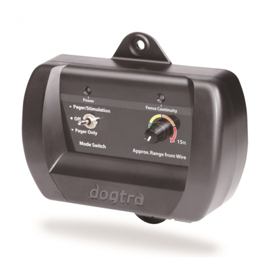
1. To ensure that your E-Fence
3500 system is working
properly, connect the power
adaptor into the transmitter
power jack and then plug the
power adaptor into a household
outlet. Switch the stimulation
knob to Pager + Stimulation,
or Pager Only. The On/Off
indicator light should turn on.
Installation
Fence Wire
The e-fence boundary wire must make a continuous loop around
your property for the system to operate. The signal is delivered
from the terminal of the transmitter, through the fence wire, back to
the other terminal on the transmitter. When this is accomplished,
the wire continuity light will emit a constant red indicator.
17
