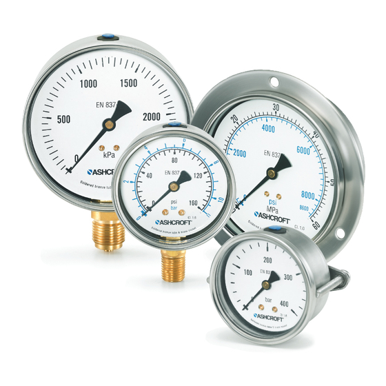
Ashcroft 8008 Einbauanleitung - Seite 2
Blättern Sie online oder laden Sie pdf Einbauanleitung für Messgeräte Ashcroft 8008 herunter. Ashcroft 8008 2 Seiten. Pressure gauge

Installation Instructions
for ASHCROFT
8008
®
Pressure Gauge
5. FRONT FLANGE AND U-CLAMP MOUNTING
Installation Instructions for 8008 Front Flange Mounting Kit
1. Align any screw hole with gauge fill plug and press flange
onto back of case until it touches front ring. To prevent
warping, press evenly around perimeter of flange as it forms
around case.
2. Drill panel hole for gauge, and drill 3 clearance OR tapped
holes (120° apart) for mounting screws (see table for sizes).
3. Use hardware provided to secure gauge to panel.
NOTE: Use an open end wrench on the gauge process
connection when connecting gauge to pressure source.
Gauge
Kit
Size
Part No.
63mm
101A230-03
2.60˝ (66.0mm)
100mm
101A230-04
4.06˝ (103.0mm) 4.15˝ (105.4mm)
Installation Instructions Type 8008 U-Clamp Mounting Kit
1. Drill panel hole for gauge (see table for sizes).
2. Place gauge through panel. Assemble bracket onto process
connection using square keyway, then shift bracket to
engage into groove of process connection.
3. Install screws (provided) through bracket and tighten onto
panel until gauge is secure (5 - 7 in-lbs).
NOTE: Use an open end wrench on the gauge process
connection when connecting gauge to pressure source.
Gauge
Kit
Size
Part No.
63mm
101A230-01
2.52˝ (64.0mm)
100mm
101A230-02
3.98˝ (101.0mm) 4.02˝ (102.0mm)
© 2016 Ashcroft Inc., 250 East Main Street, Stratford, CT 06614-5145, USA, Tel: 203-378-8281, Fax: 203-385-0357, www.ashcroft.com
All sales subject to standard terms and conditions of sale. I&M008-10248 Letter (8008) 09/16
Panel Hole
Min
Max
2.70˝ (68.8mm)
Panel Hole
Min
Max
2.56˝ (65.0mm)
Bolt
Screw
Circle
Clearance
2.95˝ (75mm)
.150˝ (3.8mm)
4.65˝ (118mm)
.201˝ (5.1mm)
(Panel)
(Panel)
(63mm Bracket)
(63mm Bracket)
Panel
Tap Hole/Thread Size
.1065˝/#6-32 UNC
.159˝/#10-32 UNF
(Panel)
(63mm Bracket)
(100mm Bracket)
(100mm Br
(100mm Bracket)
