DoorKing 2334-080 Manual - Página 2
Navegue en línea o descargue pdf Manual para Unidad de control DoorKing 2334-080. DoorKing 2334-080 3 páginas. Voip / rs-232 control box
Wiring
AFTER DKS Online Registration Completed,
VoIP/RS-232 Board will function.
See previous page.
The EARTH GROUND must be connected to a
proper ground close by (ground rod, cold water
pipe in the ground, existing electrical ground, etc).
Battery Back-Up
Call DoorKing
PHONE
RJ11
CHRG
Reset Timer Selector
BATTERY
BATT
OFF-OFF = No reset
OFF-ON = 1 day
ON-OFF = 2 days
ON-ON = 3 days
ON
1
2
SW3
Reset Links
RESET LINKS
2334-010
P1
P2
Cat5
Cat5 cable to Your Router
connected to the internet
See previous page.
Cat5 Cable
TCP/IP Camera
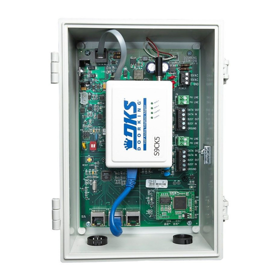
Box Installation
k e t
r a c
g B
a r e
t i n
r d w
u n
M o
H a
a n d
g
t i n
u n
M o
t
c k e
B r a
a n d
a r e
r d w
H a
W i
n
R u
r e
W i
included). IT IS NOT RECOMMENDED DRILLING
HOLES IN THE PLASTIC ENCLOSURE!
If holes must be drilled, remove the circuit board before drilling and be sure that
mounting bolts/screws do not touch the back of the circuit board. Holes must be
sealed to prevent water intrusion.
2334-065-C-6-18
RS 232 Connection
System A
Terminal
DATA OUT-Red
DATA IN-Black
BUSY OUT-White
BUSY IN-Brown
GROUND-Green
Supplied Power
16.5VAC
Transformer
40 VA
Reset VoIP
ONLY
VOIP
16VAC
Power
16VAC
PHONE
RESET
12 VDC
DC
E GND
POWER
VoIP Adapter
PH LINE
PH LINE
DATA OUT
RS-232
DATA IN
BUSY OUT
"A"
BUSY IN
GROUND
RS 232
PH LINE
PH LINE
DATA OUT
DATA IN
RS-232
LAN (Cat5)
BUSY OUT
BUSY IN
"B"
GROUND
RS 232
DATA
LINK
P3
Cat5
Cat5
DKS
TCP/IP
DKS TCP/IP
Adapter
RS 232 Connection
System B
1830
Terminal
Terminal
DATA OUT-Red
DATA IN-Black
BUSY OUT-White
BUSY IN-Brown
GROUND-Green
Jumper
MUST be
Moved
The plastic enclosure
n
R u
comes with mounting
r e
brackets and hardware to mount
on enclosure. Mount enclosure on
surface using appropriate hardware (not
RS 232
1
2
1830
RS 232
3
4
Terminal
5
6
1
2
3
4
5
FEED
BACK
3 2 1
2
HF
HS
Earth
Ground
Voice
Twisted Pair
MUST be used.
Choose How to Power VoIP/RS-232 Board:
1
Wire supplied power transformer (16.5 VAC, 40 VA) to Aux
terminal 1 & 2, wire VoIP/RS-232 power terminal to Aux terminal
5 & 6. This powers VoIP/RS-232 board AND DoorKing phone entry
system's Aux terminal. If Aux terminal 1 & 2 is already being
powered by a 16.5 VAC, 20 VA transformer, REPLACE IT with the
16.5 VAC, 40 VA transformer that is supplied to power BOTH devices.
NOT available on the 1834.
1
2
3
2
Wire supplied power transformer (16.5 VAC, 40 VA) DIRECTLY
4
to VoIP/RS-232 power terminal.
5
RS 232
1
2
RS 232
3
4
5
6
FEED
BACK
3 2 1
HF
HS
PHONE
Voice
System B Phone Line Alternate Use - If system B is not being used for a
second phone entry system, a phone can be installed and used. It shares the
phone line with the System A phone entry system. The phone cannot be
used while a transaction is taking place on System A.
2
SYSTEM A
1830
Voice/Data system
should be as close as
possible to SYSTEM A.
MIC
VOL
3 2 1
SPK
VOL
Jumper
MUST be
Moved
ON
MASTER
CODE
OFF
KEYPAD
NO
RING
Main Terminal
PHONE
CGND
PSW
MIC
COM
SPKR
IMD
5VDC
IMC
Z
A
2C
2RY
1C
18 AWG Min. Power Wire
Do Not Connect
Power To A
Receptacle
Controlled By
A ON/OFF Switch.
- OR -
DO NOT wire to Aux terminal 5 & 6.
SYSTEM B
Optional 1830
TWO Entry Systems - The Voice/Data
system can supply telephone service and
programming for TWO 1830s designated
as System A and System B.
The telephone line is SHARED with both
3
1830s. Each 1830 MUST be programmed
SPK
VOL
for Multiple Systems, see specific 1830
Installation/Owner's instruction manual
for more information.
ON
MASTER
CODE
OFF
KEYPAD
NO
RING
CGND
PSW
MIC
COM
SPKR
IMD
5VDC
IMC
Z
A
2C
2RY
1C
ELEVATOR
1
2
3
Aux
5 & 6
Terminal
NC
1NC
1NO
BAT
16AC
16AC
1
ONLY
Supplied Power
Existing
Transformer
Power
16.5VAC
16.5VAC
40 VA
20 VA
1
ONLY
ELEVATOR
1
2
3
NC
1NC
1NO
BAT
16AC
16AC
16.5VAC
16.5VAC
20 VA
20 VA
Existing Power