DPCAV PANDORA Manual - Página 5
Navegue en línea o descargue pdf Manual para Unidad de control DPCAV PANDORA. DPCAV PANDORA 7 páginas. Pan & tilt kit

Bottom Mount (Under-Carriage) Assembly:
Note: Carefully review the photos shown below for details to the following assembly steps.
1.
Install the HS-65HB (or generic 9-Gram) servo on the chassis's side panel (item 2) using two
2-56 x 3/8" machine screws and nuts, as well as the grommets supplied with the servo. Be
sure to apply Threadlocker to the threads.
2.
Using two 2-56 nuts (with Locktite), install
the tilt plate (item 9) onto the main chassis.
Do NOT tighten the axle nuts. Verify
correct axle placement so that the tilt plate
can smoothly swing up and down. Please
note that this configuration uses the
forward axle mounting holes, as seen in
Figure 10.
3.
If a HS-65HB servo is used, then install its
one-inch long nylon arm. Alternate: When
a generic 9-gram servo is used, the red
servo arm (item 11) is installed on the
servo's nylon wheel. Drill the wheel's holes
with a 0.064" bit and install the red arm
with two 2-56 x 1/4" self tapping screws.
Please see Figure 10 for details.
4.
Install a DuBro mini EZ pushrod connector on the arm (drill a hole for the EZ using a 0.060"
bit). Please note that the "lower" pushrod hole is used in this configuration.
5.
Install the pushrod as shown in the photos. The Z-bend end is placed on the Tilt panel side.
Warning: The servo arm position must be made with care to prevent damage to the servo
when it travels to its extreme positions. It will be necessary to adjust your R/C system's
EPA/ATV mix for the proper servo range.
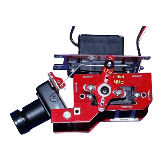
Figure 12, Camera Full Forward
P
(
), www.dpcav.com
ANDORA
REV-C
Figure 11, "Bottom" Mount Details
Figure 13, Camera Full Down
Page 5
©2007-2008 Jun-11-2008
