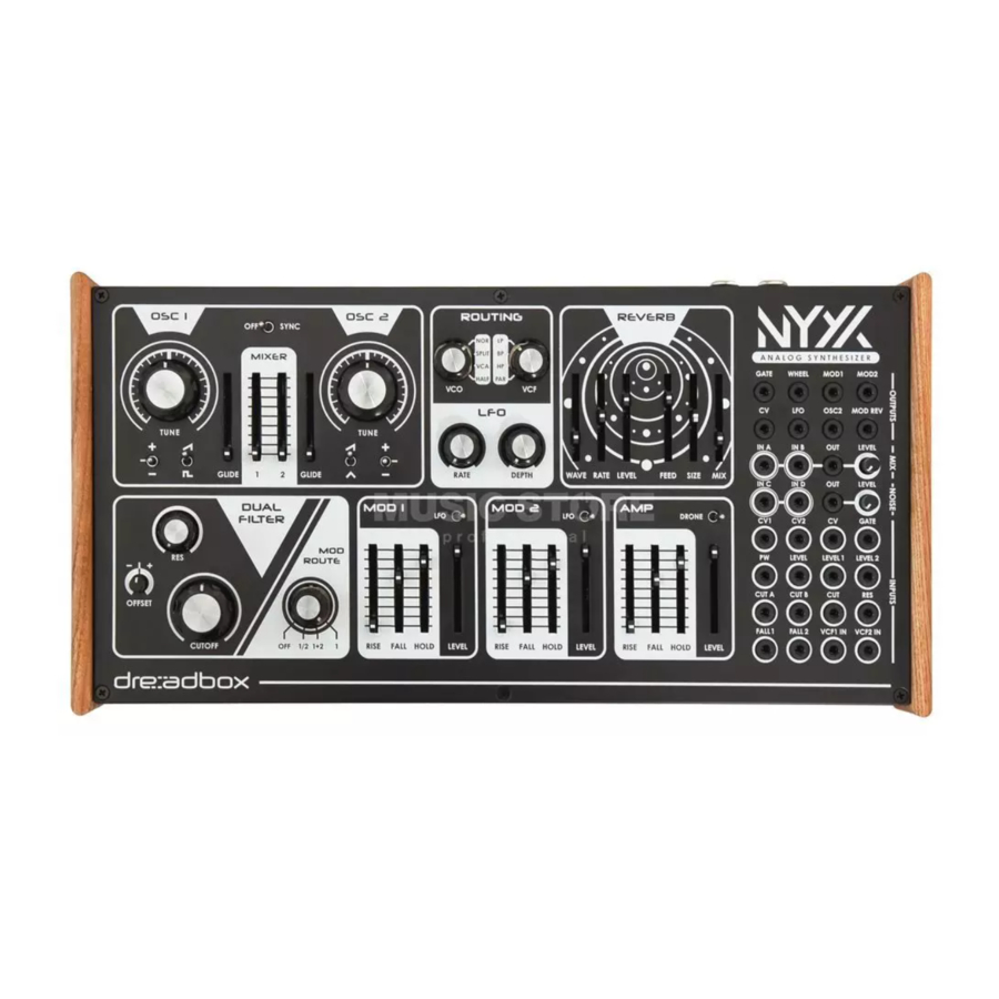
Dreadbox Nyx V2 Manual del usuario - Página 10
Navegue en línea o descargue pdf Manual del usuario para Sintetizador Dreadbox Nyx V2. Dreadbox Nyx V2 14 páginas. Analog, 2 oscillators, 12-24db dual filter, 2 function generators, extensive digital reverb, 30 eurorack patch points
También para Dreadbox Nyx V2: Manual de sintonización (3 páginas)

The Patch Bay
The Nyx V2 has 30 patch points, offering endless routing and modulation possibilities.
The Patch Bay is consisted of 4 major parts:
GENERAL OUTPUTS
1. GATE : outputs the gate CV (0-6.5V pulse)
2. WHEEL : outputs the modulation wheel CV (0-5V)
3. MOD1 : outputs the Modulator 1 CV (0-5V)
4. MOD2 : outputs the Modulator 2 CV (0-5V)
5. CV : outputs the MIDI notes to CV (0-10V) over 10 octaves
6. LFO : Direct output of the LFO. When patching this, the effect on
the pitch of the oscillators will be cancelled. (+/- 3V)
7. OSC2 : outputs the selected wave of the OSC2 (+/- 5V)
8. MOD REV : outputs Reverb Modulation CV. Always at max level
(+/- 5V)
MIX
9-12. IN A, IN B, IN C, IN D : mixer inputs (+/- 10V max)
13. OUT: outputs the sum of IN A, IN B, IN C, IN D
LEVEL : sets the level of the mixer's output (+/- 10V max)
NOISE
14. OUT : white noise (+/- 5V max)
LEVEL : sets the level of the White Noise
INPUTS
15. CV1 : OSC1 CV input 1V/oct (+/- 2% off to precision) (+/-10V)
16. CV2 : OSC2 CV input 1V/oct (+/- 2% off to precision) (+/-10V)
17. CV : OSC1 and OSC2 CV input 1V/oct (+/- 2% off to precision) (+/-10V)
18. GATE : expects a 0 to 5V pulse so as to handle as a Gate signal. (can accept from 3.3V up to 10V)
19. PW : pulse width control over the square wave of OSC1
20. LEVEL : controls the amplitude of both OSC1 and OSC2 (+/-5V)
21. LEVEL1 : controls the amplitude of OSC1 (+/-5V)
22. LEVEL2 : controls the amplitude of OSC2 (+/-5V)
23. CUT A : controls the Cutoff frequency of Filter1 (+/-5V)
24. CUT B : controls the Cutoff frequency of Filter2 (+/-5V)
25. CUT : controls the Cutoff frequency of both Filter1 and Filter2 (+/-5V)
26. RES : controls the amount of the resonance (+/-5V)
27. FALL1 : controls the fall rate of the MOD1(+/-5V)
28. FALL2 : controls the fall rate of the MOD2(+/-5V)
29. VCF1 IN : audio input on VCF1
30. VCF2 IN : audio input on VCF2
10
