Atkinson Electronics GSCM Instrucciones de uso e instalación - Página 7
Navegue en línea o descargue pdf Instrucciones de uso e instalación para Unidad de control Atkinson Electronics GSCM. Atkinson Electronics GSCM 16 páginas. Generator start control module
También para Atkinson Electronics GSCM: Manual (16 páginas)

GENERATOR START CONTROL MODULE
GENERATOR EMERGENCY SHUTDOWN WITH THE GSCM
The GSCM Generator Start Controller is NOT AN EMERGENCY SHUTDOWN DEVICE!! Shorting the reset terminals 7 and 8
terminates the current GSCM cycle (see Section 5). If the manual start signal is removed the generator will go through a normal
shutdown which may include running for up to two minutes in a "load removed" cool-down cycle. Also shorting reset terminals
7 and 8 will shutdown the generator in a normal sequence including the cool-down cycle. If the generator has started but is in
the "load delay period", applying a reset to terminals 7 and 8 will shutdown the generator immediately.
A RECOMMENDED EMERGENCY SHUTDOWN SOLUTION is to install a separate "Kill" switch and label it as such. The
recommended wiring is shown on page-2 of these instructions and also in Application 1. Disconnecting the power to the GSCM
module will force the relays to open. This will shutdown generators that require a maintained run signal from K3 (ignition) relay.
However this also prevents the K4 (shutdown) relay from closing to shutdown those generators requiring a momentary stop signal.
Using a double pole "Kill" switch and wiring the second pole in parallel with the K4 (shutdown) relay terminals will force the
generator to stop in an emergency situation such as a fuel spill.
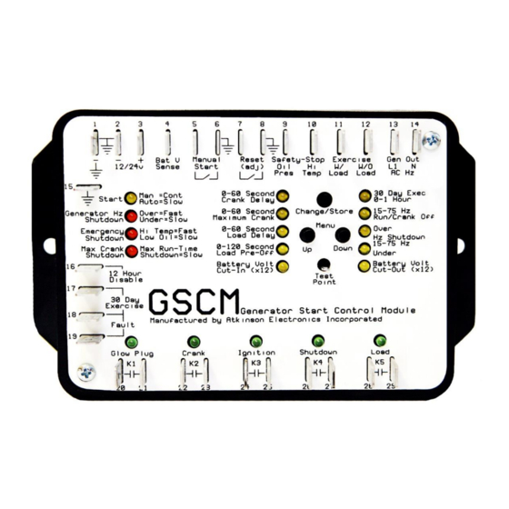
LED DESCRIPTION (WHAT THEY MEAN)
OPERATION LEDS:
1.
continuous = manual start signal received; one blink every 5 seconds = ready to receive a command;
Start:
slow blink = auto start mode operation; fast blink = 60 second delay after reset, before "ready" mode
2.
Generator Hz Shutdown:
3.
Emergency Shutdown:
4.
Max. Crank Shutdown:
ADJUSTMENT & TIMING LEDS:
1.
0-60 Second Crank Delay:
2.
0-60 Second Maximum Crank:
3.
0-60 Second Load Delay:
4.
0-120 Second Load Pre-Off:
5.
Battery Charge Cut-In (x12):
6.
Battery Charge Cut-Out (x12):
7.
15-75Hz Under Hz Shutdown:
8.
15-75Hz Over Hz Shutdown:
9.
15-75Hz Run/Crank Off:
10. 0-1 Hour 30 Day Exercise:
ATKINSON ELECTRONICS, INC.
Web Site: www.atkinsonelectronics.com
fast blink = over speed; slow blink = under speed
continuous = start function disabled, AC Hz detected before starting
fast blink = high temperature; slow blink = low oil pressure
fast blink = max. 4 crank attempts exceeded; slow blink = 12 hour max. runtime exceeded
continuous = adjustment selection;
blinking = entered crank delay period while glow plug relay K1 energized
continuous = adjustment selection;
blinking = rest period after unsuccessful cranking attempt
continuous = adjustment selection;
blinking = generator running, delay period before load transfer
continuous = adjustment selection;
blinking = load disconnected, cool down period before shutdown
continuous = adjustment selection;
blinking = battery voltage lower than cut-in point, during 5 minute delay
continuous = adjustment selection;
blinking = battery voltage greater than cut-out point, during 10 minute delay
continuous = adjustment selection;
blinking = generator Hz (under speed) less than trip point, during 10 second delay
continuous = adjustment selection;
blinking = generator Hz (over speed) greater than trip point, during 10 second delay
continuous = adjustment selection; no blinking condition
continuous = adjustment selection;
one blink every minute = 30 day exercise option activated;
fast blink = 60 second warning before 30 day exercise generator starting
Distributed by:
GSCM
SECTION - 6
SECTION - 7
REV 8/06
