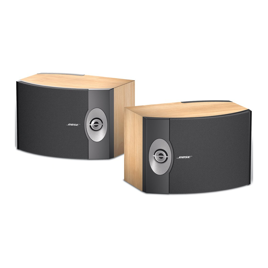
Bose 301 Series V Manual del usuario - Página 5
Navegue en línea o descargue pdf Manual del usuario para Altavoces Bose 301 Series V. Bose 301 Series V 10 páginas. Direct/reflecting speakers
También para Bose 301 Series V: Manual del usuario (13 páginas), Manual del usuario (12 páginas), Manual del usuario (12 páginas), Manual del usuario (21 páginas), Manual del usuario (13 páginas), Manual del usuario (16 páginas)

Note: Remove the grille for the following
tests.
General Test Set Up
Connect the output of a signal generator to
the input of a power amplifier. Connect the
output of the power amplifier to the input
terminals of the speaker under test. Refer
to figure 2, (on page 4) test equipment set
up.
1. Woofer Rub and Tick Test
1.1 Apply a 7 Vrms, 10 Hz signal to the
input terminals of the speaker under test.
No extraneous noises such as rubbing,
scraping or ticking should be heard.
Note: To distinguish between normal sus-
pension noise and rubs or ticks, displace
the cone on the woofer slightly with your
fingers. If the noise can be made to go
away or get worse, it is a rub or a tick and
the woofer should be replaced. If the noise
stays the same, it is a normal suspension
noise and the woofer is fine. Suspension
noises will not be heard with program
material.
2. Air Leak Test
2.1 Apply a 7 Vrms, 35 Hz signal to the
input terminals of the speaker under test.
2.2 Listen for air leaks around the woofer,
tweeters and cabinet seams. Any air leaks
will be heard as a sputtering or hissing
sound.
2.3 Replace or reposition any gasket where
an air leak can be heard.
3. Sweep Test
3.1 Apply a 7 Vrms, 10 Hz signal to the
input terminals of the speaker under test.
TEST PROCEDURES
5
3.2 Sweep the input generator from 10 Hz
to 5 kHz. There should be no extraneous
sounds.
3.3 Reduce the input voltage to 3 Vrms, and
continue sweeping from 5 kHz to 15 kHz.
3.4 Redress any wires or components that
buzz or rattle. Replace any woofer or
tweeter that is found to be defective.
4. Phase Test
Note: The supply voltage should only be
momentarily applied to the speaker input
terminals to avoid possible damage to the
speaker.
4.1 Set a DC power supply to 9 volts.
Connect the positive wire from the power
supply to the positive (+) connector of the
input terminal and the negative wire to the
negative (-) connector of the input terminal.
The woofer should move outward with the
application of the supply voltage.
