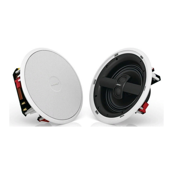
Bose Virtually Invisible 791 Manual de instalación - Página 5
Navegue en línea o descargue pdf Manual de instalación para Altavoces Bose Virtually Invisible 791. Bose Virtually Invisible 791 23 páginas. Installation guide
También para Bose Virtually Invisible 791: Manual de instalación (17 páginas), Manual de instalación (35 páginas)

Selecting speaker cable
If your cables are not yet installed, use these guidelines
for choosing and using speaker cable. If your cables are
already installed, check to be sure they meet these
standards.
Gauge
Maximum Length
18 AWG (0.82 mm
2
)
20 ft (6 m)
16 AWG (1.3 mm
2
)
30 ft (9 m)
14 AWG (2.1 mm
2
)
50 ft (15 m)
12 AWG (3.3 mm
2
)
90 ft (27 m)
Consider the location of the speakers and be sure to
allow enough cable to reach each one. This includes the
extra length needed for wiring the speaker before
inserting it into the ceiling.
PREPARATION
Preparing the cable wires
Speaker cable consists of two insulated wires. The
insulation around one wire is marked (striped, collared,
or ribbed) to identify it as positive. The other wire is
negative.
Note: It is sometimes difficult to distinguish wire
markings. Inspect both wires carefully.
1. Strip approximately '/2 in. (13 mm) of insulation from
both wires.
2. Twist the bare end of each wire so loose strands will
not touch across terminals.
Be sure to connect each wire to the proper speaker
terminal, positive to positive (+) and negative to
negative (-).
Note: For information on installing cable, consult
a
professional electrician
or
audio/video installer,
or
look
for reference books at
a
local home building retail store.
3
