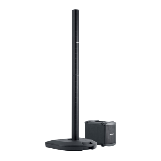
Bose Personalized Amplification System Manual de solución de problemas - Página 19
Navegue en línea o descargue pdf Manual de solución de problemas para Sistema estéreo Bose Personalized Amplification System. Bose Personalized Amplification System 50 páginas.
También para Bose Personalized Amplification System: Manual del usuario (28 páginas)

THEORY OF OPERATION
Input "combo-jacks" J101 and J102 [C1, A1] are configured so that outputs from buffer amps
U101A & U103A are shorted to ground when a ¼" plug is not inserted into J101 or J102 – this
eliminates the OpAmps's noise contribution when the Mic input is in use, or when the channel is
not being used. U101B and U103B provide "DC servo" feedback to the INA163's to effectively
null out any DC that would appear on their outputs.
Phantom Power
Condenser microphones are popular for many applications; they require a balanced external
power source applied equally to pins 2 & 3 of the XLR-type microphone connector. In addition
to an on/off switch and pilot LED, additional circuitry is provided to enable the +24VDC Phantom
power supplies to ramp up and down at a relatively slow rate, thereby preventing turn-on and
turn-off pops and clicks.
1.5.3 Line Out
The Ch1 and Ch2 XLR balanced Line Outputs are driven by OpAmps U106 and U107 [A6, C6].
These stages translate the internal PreAmp output signal to a differential balanced output.
1.5.4 Digitally Controlled Analog Volume
Ch1 and Ch2 Volume controls are implemented though a Toshiba TCA9459F chip, U302 [micro-
processor PCB sheet 1, C3]. This chip contains a resistor ladder and a series of analog switches
that attenuate the input according to serial commands from the microcontroller. Attenuation of
0dB to -89dB (plus "off") is available in steps of 1dB, but the PS1's software contains a look-up
table to access a subset of these steps. This optimizes the feel of the control over the range of
0 to -40dB. The range is restricted to prevent the user from inadvertently turning the signal path
completely off.
1.5.5 Channel Insert
J105 and J106 [input panel PCB sheet 1, B5] are stereo ¼" jacks configured with the output
("Send") connected to the Ring terminal, and the input ("Return") connected to the tip. Usually,
this would be used with a special "insert Y-cord" to route the Ch1 or Ch2 signal to an external
effects device such as a reverb, chorus, etc. If a 2-conductor (mono) ¼" plug is fully inserted,
the signal will be routed directly into the A/D converter, bypassing all of Ch1 or Ch2's PreAmp
and Channel Volume control circuitry.
1.5.6 Channel 3 & 4 Inputs
The input signals are received through J107 [C8] /J108 [A8]. These are unbalanced 1/4" jacks
which short the input to ground if nothing is inserted. The signal is attenuated by VR103/VR104,
AC coupled, buffered and amplified through U108A/U108B and then routed to the A/D converter
U385 [DSP PCB sheet 1, D5] (Crystal CS5361). Because there is no active circuitry between
the inputs and the level controls, judicious setting of the controls can allow Ch3 and Ch4 to
accept very high input levels.
1.5.7 Analog to Digital Converters (Analog)
The PS1 has two stereo A/D converters Crystal CS5361. U386 [C5] receives channels 1 and 2,
U385 receives channels 3 and 4. Each channel signal is received on the DSP board through
CN104 [B1]. Each signal is AC-coupled, buffered and balanced through op-amp pairs (U381A/B
– U384A/B). All eight resulting signals are clipped with diode pairs and routed to the A/D chips.
19
