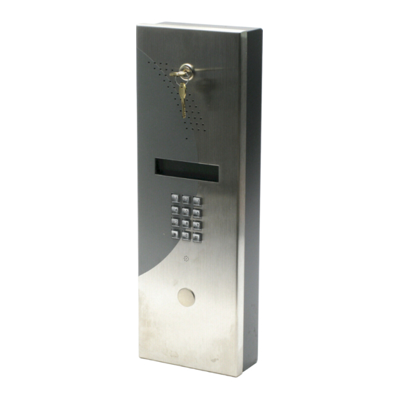
DSC MAXSYS PC4850 Manual de instalación - Página 12
Navegue en línea o descargue pdf Manual de instalación para Unidad de control DSC MAXSYS PC4850. DSC MAXSYS PC4850 16 páginas. Telephone entry module

1. Enter [*][8][Installer Code].
2. Enter reference number [0017XX00], where XX is the
number of the PC4850 module.
3. Use the arrow (<>) keys to scroll until the display
shows:
No Bill
4. Press [*] to toggle the option on or off.
5. When you are finished, press [#].
3.9 Changing the Battery Supervision Option
Ref #: [0017XX00], where XX = PC4850 module number
You can choose to have the PC4850 supervise the battery.
If the PC4850 supervises the battery, it will send the
panel a battery trouble when the battery is low.
1. Enter [*][8][Installer Code].
2. Enter reference number [0017XX00], where XX is the
number of the PC4850 module.
3. Use the arrow (<>) keys to scroll until the display
shows:
Battery Suprvs
4. Press [*] to toggle the option on or off.
5. When you are finished, press [#].
3.10 Setting the Talk Time, Door Time, Auxiliary
Relay, and the Call Time
Ref #: [0017XX01], where XX = PC4850 module number
You can change the settings for:
• length of time users can talk to visitors (Talk Time);
• length of time the door unlocks when a user presses [7]
on their telephone (Door Time);
• length of time for the auxiliary relay when a user
presses [9] on their telephone (Aux Rly Time).
Example: the auxiliary relay could control a gate to a
car entrance;
• the amount of time the PC4850 will wait for the user to
pick up the phone before canceling the call (Call Time).
To change any of these settings follow the steps below.
1. Enter [*][8][Installer Code].
2. Enter reference number [0017XX01], where XX is the
number of the PC4850 module.
3. To change the Talk Time, press [00].
To change the Door Time, press [01].
To change the Aux Rly Time, press [02].
To change the Call Time, press [03].
4. Enter the new 3-digit time for the timer you selected
(000-255 seconds).
5. Repeat steps 3 and 4 until you have programmed all
the timers.
NOTE: When using the No Bill option, the Call Time
should not be set for more than 60 seconds.
8
3.11 Setting up Access Codes for Two Building
Entry Points
Ref #: [0017XX02], where XX = PC4850 module number
The PC4850 can control two entry points (e.g., a door and
a car gate) using the door strike and the auxiliary relay
circuits. If the users will be using access codes to enter
the building, you can assign one set of codes to one entry
point and another set of codes to the second entry point.
To do this, tell the PC4850 what the last code will be for
the first entry point – this is the Entry Access Divider. For
example, if you set the divider to be 4999, codes from
0001 to 4999 will open the first entry point (e.g., the
building's main door), and codes 5000 to 9999 will open
the second entry point (e.g., the car gate).
NOTE: With the setting (9999), none of the entry
access codes will open the 2nd entry point.
NOTE: When using the Entry Access Divider with a 6-
digit access code, only the first four digits of the
access code are used to determine which entry point
is unlocked.
To set the Entry Access Divider:
1. Enter [*][8][Installer Code].
2. Enter reference number [0017XX02], where XX is the
number of the PC4850 module.
3. Enter the 4-digit code that will be the divider
between the two access points. Valid entries are 0000
to 9999.
4. When you are finished, press [#].
3.12 Resetting to Factory Default Programming
You can reset all the PC4850 programming to factory
default settings.
To do this, create a temporary short on jumper J2 on the
PC4850 circuit board.
1. Power down the PC4850.
2. Create a short on J2.
3. Power up the PC4850.
4. Wait 10 seconds and remove the short.
NOTE: Cell phones shall not be programmed to allow
access.
