cashco 988 Manual de instalación, uso y mantenimiento - Página 4
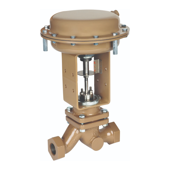
Navegue en línea o descargue pdf Manual de instalación, uso y mantenimiento para Unidad de control cashco 988. cashco 988 20 páginas. Globe-style pneumatic control valve body

SYSTEM UNDER PRESSURE. Prior to performing any
main te nance, isolate the valve/actuator from the system
and re lieve all pressure. Failure to do so could result in
personal in ju ry.
V. MAINTENANCE
A. General:
1.
Maintenance procedures hereinafter are based
upon re mov al of the valve/actuator unit from the
pipeline where in stalled.
2.
Owner should refer to Owner's procedures for
re mov al, han dling and cleaning of non-reusable
parts, i.e. gaskets, suit able solvents, etc.
3.
Valves supplied from the factory do not use any
aid to assist in gasket sealing such as oil, sealant
or pipe dope. Owner may use such aids provided
the aids are com pat i ble with the Owner's fluid.(See
below for "oxygen cleaned" valves.)
4.
Valves originally supplied per Option-55 require
special clean ing procedures. Refer to Cashco
Spec i fi ca tion No. S-1134 for details. When in
com pli ance with/to Spec. No. S-1134, the valve
is suit able for oxygen service. This procedure is
limited to bodies of SST or HC only.
5.
All indicated Item Numbers that are with respect to
the actuator assembly (AA) will be in parenthesis
and un der scored; i.e. (20); All Item Numbers that
are with respect to the body assembly (BA) are not
underscored; i.e. (32).
6.
Special care must be exhibited when rotating
the plug/stem (3) of the valve to not mar that
portion of the surface of the stem where it
contacts with the packing (6). To rotate the
plug/stem use the jam nuts (52) or a soft jawed
pliers. NOTE: When using the jam nuts to rotate
the plug/stem, use the upper jam nut to rotate the
stem CW, and the lower jam nut to rotate the stem
CCW, when viewed from above valve plug/stem.
7.
Hereafter, whenever text has the following notation,
(Note PA.)
"
"For ATO-FC units ONLY,
temporary air source with gauge to the actuator
and pressurize to a level sufficient to initiate
travel to approximately mid-stroke."
8.
Hereafter, whenever text has the following notation,
"(Note RP.)", the following text is to be applied:
"For ATO-FC units ONLY,
temporary air pressure."
4
WARNING
", the following text is to be applied:
connect a
release all
SECTION V
B. Actuator Assembly Removal:
1.
Refer to the correct actuator IOM for this pro ce dure.
2.
Secure the (BA) in vise with (AA) oriented vertically.
3.
Rig (AA) to be supported above the (BA). Place
matchmarks between the bonnet/yoke and yoke/
ac ces so ry plate.
4.
This procedure assumes that the (BA) is fully
assembled through the bonnet (2), in clud ing the
pack ing flange (4), fol low er (5), and packing (6).
5.
(Note PA.) Securing the "flats" of the actuator
stem (6) by wrench, loos en stem jam nuts (52) by
rotating CW (viewed from above) one-at-a-time.
6.
Fully loosen any accessory devices that are
con nect ed to/with the stems (6), (3), such as
ac ces so ry plate ((AP)) for limit switch or positioner.
If actuator has handwheel - see Actuator IOM for
removal instructions.
7.
Using a blunt end tool, hammer rap the tool to
loos en yoke nut (25), turning CCW (viewed from
above) approximately 1/2 revolution.
8.
If the actuator is to be reinstalled, put paint or dye
mark er between the plug/stem (3) and the ac tu a tor
stem (6), to serve as matchmarks.
9.
Loosen packing (6) by rotating nuts (15) CCW 2-3
revolutions. (Note RP).
NOTE: To fully disengage the actuator stem (6) from
the plug/stem (3) is a two-step procedure. Be aware
of the valve's stroke length as indicated on the
name plate (40) before beginning dis en gage ment.
During the dis en gage ment, measure the distance
ex tend ed and attempt to make each step about
half of full stroke. Keep track of the num ber of
rev o lu tions for each step in the box below.
For Steps 10A and 10B: Count the Number
of revolutions to disengage plug/stem from actuator stem:
Step A. __________
TOTAL ________
10A. For ATO-FC Reverse Action Actuators:
a.
(NOTE PA).
b.
Step A. Rotate plug/stem (3) CW (viewed from
above the valve) to disengage the actuator
stem from the plug/stem. Record number of
plug/stem revolutions for Step A in box above.
When dis en gage ment reaches ap prox i mate ly
50% of full stroke travel, Step A is complete.
Step B. _________
IOM-988/989-BODY
