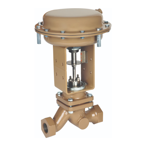
cashco 988 Manual de instalación, uso y mantenimiento - Página 5
Navegue en línea o descargue pdf Manual de instalación, uso y mantenimiento para Unidad de control cashco 988. cashco 988 20 páginas. Globe-style pneumatic control valve body

c.
Step B. Support the (AA) from above. Fully
loosen yoke nut (25) to re mov al. Lift the (AA)
up wards approximately 1/4"–3/8" (6–8 mm).
Again, ro tate plug/stem (3) CW (viewed from
above) until dis en gage ment from actuator
stem (6). Record num ber of plug/ stem
revolutions for Step B in box on previous page.
NOTE: Take notice of the parts "dangling loosely"
about the stem, the order of their location and their
proper orientation.
d.
Fully raise (AA) above (BA). Remove carefully
to prevent "dangling parts" (position indicating
washer (51), accessory plate ((AP)), yoke nut
(25)) from falling.
10B. For ATC-FO Direct Action Actuators:
a.
Step A. Rotate plug/stem (3) CW (viewed from
above the valve) to disengage the actuator
stem from the plug/stem. Record number of
plug/stem revolutions for Step A in box on
previous page When dis en gage ment reach es
ap prox i mate ly 50% of full stroke travel, Step
A is completed.
b.
Step B. Support the (AA) from above. Fully
loosen yoke nut (25) to re mov al. Lift the
(AA) up wards approximately 1/4"–3/8" (6–8
mm). Again ro tate plug/stem (3) CW (viewed
from above valve) until dis en gage ment from
ac tu a tor stem (6). Record the num ber of valve
stem rev o lu tions for Step B in box on pre vi ous
page.
NOTE: Take notice of the parts "dangling loose ly"
about the stem, the order of their location and their
proper orientation.
c.
Fully raise (AA) above (BA). Remove carefully
to prevent "dan gling parts" (position indicating
washer (51), ac ces so ry plate ((AP)), yoke nut
(25) from falling.
C. Mounting Actuator Assembly to Body As sem bly:
1.
Refer to the correct actuator IOM for completion of
this pro ce dure.
2.
Secure the (BA) in a vise with the plug/stem (3)
oriented vertically. Push stem down until plug
touches the seating surface in the body.
3.
Rig (AA) to be supported above the (BA).
4.
This procedure assumes that the packing assembly
and bonnet (2) have been bolt ed to the body (1).
5.
Engage stem jam nuts (52) one-at-a-time to the
plug/stem (3) by rotating CW (viewed from above
stem end). Rotate jam nuts all the way down to the
root of the stem threads.
IOM-988/989-BODY
(Note RP).
6.
Lower (AA) until the opening of the ac tu a tor yoke
(3) is at the level of upper jam nut (52).
7.
Place yoke nut (25) over the plug/stem (3) and
lower the nut to rest upon the yoke.
8.
Place travel indicator washer (51) and accessory
plate ((AP)) over stem (3) and allow to rest upon
upper stem jam nut (52).
9.
Align matchmarks between body/bonnet, bonnet/
yoke and yoke/accessory plate. Continue to lower
(AA) until two stems are approximately 3/8" (8mm)
apart.
10.
Ensure that plug/stem (3) is resting on seat ring.
11A. For ATC-FO: Hook up a temporary air supply
hose that has an ad just able airset connected at
the actuator inlet to allow pres sur iza tion. Slowly
pres sur ize ac tu a tor to bring the actuator stem to
within 1/8" (3mm) of touching the plug/stem.
11B. For ATO-FC: Continue lowering (AA) un til
ac tu a tor's stem (6) and valve's stem (3) almost
touch.
12.
Rotate yoke nut (25) onto bonnet (2) threads as far
as able to help stabilize topworks. Wrench-tighten
one-half (1/2) extra rev o lu tion.
13.
Use hand to lift plug/stem (3) upwards to engage
with actuator stem (6). Ro tat ing plug/stem CW
(viewed from plug end) the same number of
rev o lu tions recorded to dis en gage the stem per B
Step 10A.
14.
For ATC-FO: Release air pressure from (AA).
For ATO-FC: (NOTE PA).
15.
Fully lower the (AA) down wards un til the yoke (3) is
properly positioned on the valve bon net (2). Hand-
tighten yoke nut (25).
16.
Complete the engagement of plug/stem into the
ac tu a tor stem the same number of revolutions
re cord ed to disengage the stems per B Step 10B.
(NOTE RP)
17.
Connect "dangling parts" – accessory plate (AP)
and travel indicator disc (51) – to actuator stem (6)
with stem jam nuts (52).
18.
Retighten packing flange nuts (15).
19.
Hammer rap yoke nut (25) with a blunt end tool
until tight.
20.
Check valve stem stoke by alternately pressurizing
and then de pres sur iz ing the actuator. Repeat
several times. DO NOT OVER PRES SUR IZE.
21.
Release all air pressure from (AA) and re move
temporary air supply hook up.
5
