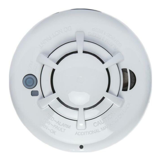
Apollo 51000-355 Manual de instalación
Navegue en línea o descargue pdf Manual de instalación para Sistema de seguridad Apollo 51000-355. Apollo 51000-355 16 páginas. Wireless smoke heat alarm

51000-355 / 51000-357
Wireless Smoke Heat Alarm
Installation Guide
ATTENTION: This manual should be read prior to use and retained for
further information.
GENERAL INFORMATION
The Wireless Smoke Heat Alarm is a 3xAAA battery powered wireless
detector intended for use with a compatible wireless alarm system. The
detector has a built-in wireless transmitter, which communicates with the
control panel. When smoke is detected, the alarm sounds a loud local alarm
and the built-in transmitter sends a signal to the control panel. The Wireless
Smoke Heat Alarm contains an integrated fixed 41°F temperature freeze
sensor that will send a warning signal based on temperature detected. This
detector is designed to provide protection with 70-foot spacing capability.
The detector can send alarm, tamper and battery condition messages to
the system's receiver. Refer to the wireless system's instruction for the
maximum number of transmitters that can be supported.
CONTENTS OF BOX:
• Wireless Smoke Heat Alarm with base
• Installation guide (APD0601)
• Pack of screws and anchors
• Labels or decals as appropriate
• 3 AAA PC2400 Duracell Procell batteries (1.5V 1100mAh) or 3 AAA
Energizer E92 batteries (1.5V 1100mAh)
The Wireless Smoke Heat Alarm contains a sounder which generates the
ANSI S3.41 temporal 3 pattern in an alarm condition. In alarm, a message
is also sent to the control panel and the detector's ID is displayed at the
console. During an alarm condition, pressing the detector's hush button
will silence the sounder (see table below). The mounting base installation
is simplified by the incorporation of features compatible for both drywall
fasteners (not supplied) and other methods.
Tricolored LED (red, yellow, green) and a sounder on the detector provide
local visual and audible indication of the detector's status as listed in Table
1.
During initial power-up the LED blinks alternately red, yellow then green. It
takes about 8 seconds for the detector to stabilize.
After power-up has completed and the detector is functioning normally, the
green LED blinks once every 12 seconds.
Detector Trouble: When the detector has a general fault, the yellow LED
blinks once every four seconds and there is a chirp every 48 seconds. After
12 hours the panel will display a loss of supervision message.
