909 BN210 Manual de instrucciones - Página 12
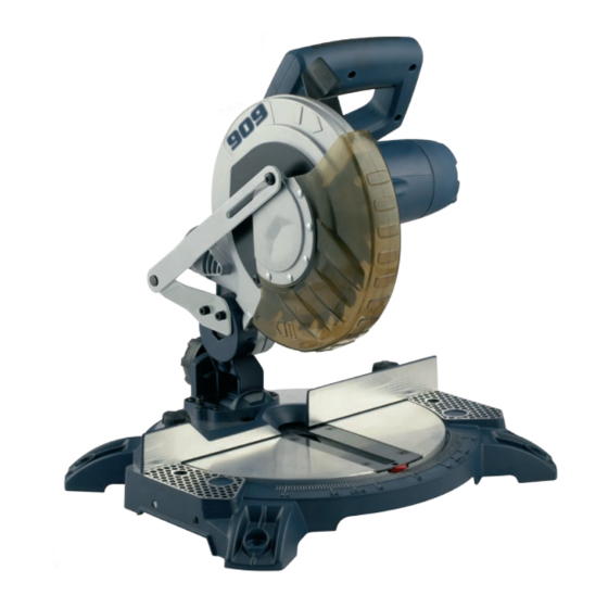
Navegue en línea o descargue pdf Manual de instrucciones para Sierra 909 BN210. 909 BN210 16 páginas. 1400w 210mm (8 1/4") compound mitre saw
Setting the fence square with the table
1. Make sure that the electrical plug is removed from the
power point.
2. Push the saw arm (1) down
to its lowest position and
engage the release knob (2)
to hold the saw arm in the
transport position.
3. Loosen the mitre locks (15).
4. Rotate the table (12) until
the pointer is positioned
at 0º.
5. Tighten the mitre locks (15).
6. Using a 5mm hex key,
loosen the two screws
securing the fence (11) to
the base (Fig. N).
7. Place a square against the
fence (11) and alongside
the blade (Fig. O).
8. Adjust the fence (11) until it
is square with the blade.
9. Tighten the screws
securing the fence (11).
10. Loosen the Phillips head
screw holding the pointer
of the mitre scale (13)
and adjust it so that it
accurately indicates the
zero position on the mitre
scale (Fig. P).
11. Retighten the screw securing the mitre scale pointer.
Changing a blade
DANGER!
Never try to use a blade larger than the stated
capacity of the saw. It might come into contact with the
blade guards. Never use a blade that is too thick to allow the
outer blade washer to engage with the flats on the spindle.
N
O
90º
P
It will prevent the blade screw from properly securing the
blade on the spindle. Do not use the saw to cut metal or
masonry. Ensure that any spacers and spindle rings that
may be required suit the spindle and the blade fitted.
1. Make sure that the electrical plug is removed from the
power point.
2. Push down on the operating handle (3) and pull the
release knob (2) to disengage the saw arm (1).
3. Raise the saw arm (1) to its highest position.
4. Using a Phillips head screwdriver loosen and remove the
Phillips head screw that secures the guard retraction arm
(6) to the rotating blade guard (5) (Fig. Q1 -Q2).
Q1
5. Using a Phillips head screwdriver loosen the Phillips head
screw that secures the blade bolt cover (19) (Fig. R).
R
6. Pull the rotating blade guard (5) down then swing it up
together with the blade bolt cover (19). When the rotating
blade guard (5) is positioned over the upper fixed blade
guard (4) it is possible to access the blade bolt (Fig. S).
12
Q2
S