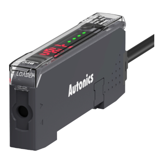
Autonics BFC Series Manual del producto - Página 3
Navegue en línea o descargue pdf Manual del producto para Media Converter Autonics BFC Series. Autonics BFC Series 4 páginas. Fiber optic amplifier communication converters

DIN Rail Mount and Removal
■ Mount
01. Hang up the holder on the backside
of the communication converter to
the DIN rail (35 mm).
02. Press the front side of the
communication converter toward
the DIN rail.
Connect and Remove Connector Cable
Caution: Do not connect the connector cable of the amplifier to the communication
converter. Otherwise, it may result in product damage.
■ Connection
Insert the connector into the
communication converter mounted to
the DIN rail with a click.
Connect Communication Converter and Amplifier
• Make sure that if you connect the side connector with excessive force, it may cause
extruded pins.
• Be sure to mount the side connector to fit tightly. Otherwise, the communication
connection may not normally work.
01. Remove the side cover (①) on the communication converter and amplifier.
02. Mount the side connector to the socket on the side of the communication
converter like ②.
03. Install the communication converter and amplifiers to the DIN rail and
gently push the communication converter toward direction ③.
04. Be sure to check the connection of the communication converter and side
connector.
①
③
Amplifier
Communication converter
Unit Descriptions
01
02
06
01. TX (transmission) indicator (red)
RX (reception) indicator (green)
02. PV display part (red 4-digit LED)
It shows the parameter.
03. SV display part (green 4-digit LED)
It shows the parameter value.
04. [◀] [▶] key
Selecting the setting value.
05. [MODE] key
Enter mode, move parameter
06. Serial communication port
Connection port for the USB/Serial converter (SCM-US, sold separately)
07. Side cover
Remove when connecting with the amplifiers
08. Connector cable terminal
Terminal for the RS485 communication / switch (SW) input mode
■ Removal
01. Slide the communication converter
to direction ①.
02. Lift the front side of the
communication converter to
direction ②.
①
②
■ Removal
Press the lever lock to the direction ①
and pull it from the communication
converter.
①
②
①
04
03
05
07
08
Parameter setting
• Return to the 2. Communication mode after the screen flashes twice.
• [MODE] key: saves the setting value and move to the next parameter,
return to the 0. Communication standby after applying the input for 3 sec
[◀], [▶] key: selects the setting value
Factory
Display
defaults Setting range
Mode
PV
SV
Communication
0
standby
WAIT
----
Communication
1
parameter
COA
PARA
Communication
2
mode
COA
485
Communication
3
address
ADR
Communication
4
speed
BPS
9600
Response
5
waiting time
RMT
6
Parity bit
PRTY
NONE
7
Stop bit
STOP
2BIT
Functions Supported by DAQMaster
If you manage the amplifiers via PC under the RS485 and serial communication,
DAQMaster supports the functions listed below. For the detailed information,
refer to the 'DAQMaster User Manual.'
• Config
It shows the number of cascaded amplifiers (BF5) with the communication converter
(BFC).
• Status
It shows the information of the cascaded amplifier (dual/single) by selecting the
channel.
• Program Group
You can change the setting values of the program mode of cascaded amplifiers.
When setting values are changed, TX and RX indicators flash and apply the changed
values to the amplifier.
• Data Bank Group
It supports data bank function, group teaching (teaching all), and initialization.
• Data Bank
It saves the settings of data bank (BANK 0, BANK 1, BANK 2).
■ Application of data bank group setting
Mode
Unit
Communication
Communication
standby
converter
Communication
converter
Bank Load
Amplifier
Communication
converter
Bank Save
Amplifier
Communication
converter
Bank Copy
Amplifier
Communication
converter
Bank Load All
Amplifier
Communication
converter
Bank Save All
Amplifier
Communication
converter
Teaching All
Amplifier
Communication
converter
Initialize
Amplifier
01) Flashing twice
• Entering method: [MODE] key 3 sec
-
485: RS485 communication
BANK: switch (SW) input
USB: serial communication
• Refer to the detailed explanation of each
mode.
1 to 99
1
1200, 2400, 4800, 9600, 192K: 19200,
384K: 38400
20 to 99 ms
• The response time may increase up to 350
ms depending on the number of connected
20
amplifiers.
None, Even, Odd
2 bit, 1bit
PV
SV
WAIT
----
LOAD
BAK0
CH01
OK
LOAD
END
LOAD
END
SAVE
BAK0
CH01
OK
SAVE
END
SAVE
END
COPY
ALL
CH01
OK
COPY
END
CH02
OK
R
OK
01)
01)
LDAL
BAK0
CH01
OK
LDAL
END
LDAL
END
01)
01)
SVAL
BAK0
CH01
OK
SVAL
END
SVAL
END
TCHI
ALL
CH01
OK
TCHI
END
TCHI
----
TCHI
END
INIT
INIT
CH01
OK
INIT
END
INIT
INIT
