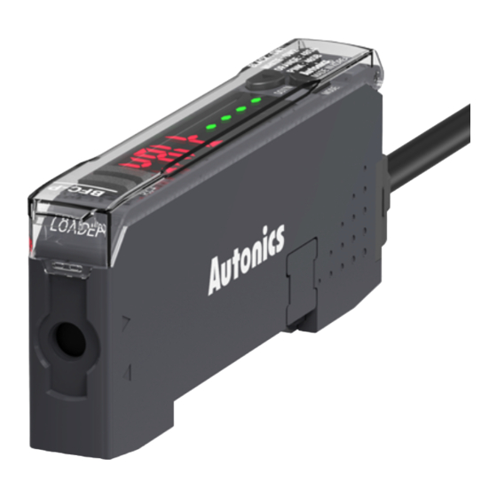
Autonics BFC Series Manual del producto - Página 4
Navegue en línea o descargue pdf Manual del producto para Media Converter Autonics BFC Series. Autonics BFC Series 4 páginas. Fiber optic amplifier communication converters

RS485 Communication
• You can manage the cascaded amplifiers via PLC or PC.
• Refer to the 'Connections' for checking the correct wire connection.
• Do not overlap the communication address on the same communication line.
• In the parameter setting, set 2. Communication mode as RS485 communication.
■ PLC connection
01. Directly connect the cables of this product to the PLC.
BFC
PLC
■ PC connection
• DAQMaster should be installed on your PC.
• Be sure to set the same communication port and address of this product and
DAQMaster.
01. Connect the cables of this product to the serial communication converters
(SCM Series, sold separately).
02. Connect the SCM Series and PC.
03. Proceed the settings via DAQMaster.
For the detailed information, refer to the 'DAQMaster User Manual.'
BFC
SCM Series
01) SCM-WF48 / SCM-US48I / SCM-38I
Switch (SW) Input
• You can change all the banks of cascaded amplifiers at once.
• You can select the BANK via signal inputs connecting with the connector cable of the
communication converter. (input time: ≥ 3 sec)
NPN
SW1
SW2
(black)
(white)
Signal standby
H
BANK 0
H
BANK 1
L
BANK 2
L
• Refer to the 'Connections' for checking the correct wire connection.
• In the parameter setting, set 2. Communication mode as switch input mode (BANK).
• The example below is based on NPN and BANK 1.
Unit
PV
SW
BANK
Communication
SET
BAK0
converter
SET
BAK1
CH01
LDAL
END
Amplifier
LOAD
END
Serial Communication
• You can manage the cascaded amplifiers via PC. DAQMaster should be installed on your PC.
• In the parameter setting, set 2. Communication mode as serial communication mode (USB).
• Be sure to set the same communication port and address of this product and DAQMaster.
■ PC connection
01. Connect the serial communication converters (SCM-US, sold separately) to the
serial communication port on this product.
02. Connect the SCM-US and PC.
03. Proceed the settings via DAQMaster.
For the detailed information, refer to the 'DAQMaster User Manual.'
PC
SCM-US
PC
01)
PNP
SW1
SW2
(black)
(white)
H
L
L
L
L
H
H
H
L
L
H
H
SV
Descriptions
SW input mode
Signal standby state, displaying the
selected BANK
SW input - SW1: L, SW2: H
OK
Change the BANK
BFC
Segment Table
The segments displayed on the product indicate the following meanings.
It may differ depending on the product.
7 segment
11 segment
0
I
0
0
0
I
1
J
1
1
1
J
2
K
2
2
2
K
3
L
3
3
3
L
4
M
4
4
4
M
5
N
5
5
5
N
6
O
6
6
6
O
7
P
7
7
7
P
8
Q
8
8
8
Q
9
R
9
9
9
R
A
S
A
A
A
S
B
T
B
B
B
T
C
U
C
C
C
U
D
V
D
D
D
V
E
W
E
E
E
W
F
X
F
F
F
X
G
Y
G
G
G
Y
H
Z
H
H
H
Z
18, Bansong-ro 513Beon-gil, Haeundae-gu, Busan, Republic of Korea, 48002
www.autonics.com | +82-2-2048-1577 | [email protected]
12 segment
16 segment
I
0
I
0
I
0
I
0
I
J
1
J
1
J
1
J
1
J
K
2
K
2
K
2
K
2
K
L
3
L
3
L
3
L
3
L
M
4
M
4
M
4
M
4
M
N
5
N
5
N
5
N
5
N
O
6
O
6
O
6
O
6
O
P
7
P
7
P
7
P
7
P
Q
8
Q
8
Q
8
Q
8
Q
R
9
R
9
R
9
R
9
R
S
A
S
A
S
A
S
A
S
T
B
T
B
T
B
T
B
T
U
C
U
C
U
C
U
C
U
V
D
V
D
V
D
V
D
V
W
E
W
E
W
E
W
E
W
X
F
X
F
X
F
X
F
X
Y
G
Y
G
Y
G
Y
G
Y
Z
H
Z
H
Z
H
Z
H
Z
-
I
J
K
L
M
N
O
P
Q
R
S
T
U
V
W
X
Y
Z
