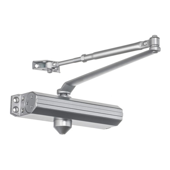
Dynasty DYN-1614 Instrucciones de instalación
Navegue en línea o descargue pdf Instrucciones de instalación para Sistema de apertura de puertas Dynasty DYN-1614. Dynasty DYN-1614 2 páginas.

PARALLEL ARM (PUSH SIDE)
P.A Plate
Power adjustment
nut
B
A
2-3/4
(70)
3/8
2
(9.5)
(51)
Door
Frame
5/16
(8) 7/16
(11)
Dimension"A"
Dimension"B"
Opening Angle
Inch
mm
Inch
mm
TO 100°
9-1/4
235
7-5/8
194
*101° TO 131°
7-3/4
197
6-1/8
156
146
4-1/8
5-3/4
105
*OVER 131°
* Recommended mounting for meeting ADA compliance
* When door closer is installed and adjusted to conform to ADA
reduced opening force requirements (5 lbs max.), it may not have
adequate closing force to reliably close and latch the door.
INSTALLATION STEPS:
1. Select degree of opening and use dimensions shown or attached template to locate 4 holes on
underside of frame for P.A plate.
2. Prepare door and frame for fasteners. See "Preparation for Fasteners", Figure 1 , Page 1.
3. Before installing closer body, set spring power for closer using Power adjustment chart, Page 1.
4. Disassemble forearm from main arm by removing elbow washer and screw.
Remove the foot from the forearm and discard.
5. Attach closer to door with Power adjustment nut toward hinge .
6. Attach P.A plate to top frame as shown.
7. Use adjustable wrench to rotate the bottom s pindle by 45° toward the hinge edge .
Hold it and Place main arm on top spindle so that the " B' (Right hand door) or ' A" (Left hand door) lines up with
spindle flat . Secure main arm and spindle by tightening spindle bolt.
8. Fasten forearm to P.A plate using screw included in screw pack.
9. When the door is closed, adjust forearm length to set arm elbow about 1-1/2"(38mm) from door when
connected to main arm. Use washer and screw provided to secure pivot connection. Tighten locknut.
10. Snap the pinion cap over spindle at the bottom of closer.
11. Adjust closer. (See Page 2)
Improper installation may result in personal injury or property damage.
!
Caution
Follow all instructions carefully please.
4
3
(76)
3/4
(19)
Speed Regulating
9-1/16
Valves
(230)
Left hand door illustrated.
Same dimensions apply to
right hand door.
Door Leaf
Measured from hinge Center.
Dimensions are in inches
1-1/2
(38)
Not To Scale
Pinion flat
For right hand door
For left hand door
door for closer body and 4 holes
Installation Selection:
Door
Frame
Door
Leaf
Regular Arm(Pull Side)
See Page 2.
Preparation for Fasteners-Figure 1.
TOOLS REQUIRED
(mm)
Closer Body
Pinion Cap
Pinion flat
How to tell the hand of a door.
Hinge side of door
Stop side of door
This is a left hand door
Door opening control
Caution:
Do not back valves out of
closer or a leak will result.
ATTENTION:
Backcheck(BC) valve controls the
hydraulic resistance to door opening in
backcheck range. NEVER close this
valve completely.
It is not to provide a positive stop.
DYN-1614,DYN-1636 DOOR CLOSER
Top Jamb(Push Side)
See Page 3.
METAL
WOOD
3/16"
#7
*Pilot Hole Required
1/4"-20
Components
P.A Plate
Foot
Elbow washer
Plastic cover
Rod
& Screw
(Optional)
Lock
Arm Screw
Nut
Screw Pack
Main Arm
Pull side
Hinge side of door
Stop side of door
Push side
This is a right hand door
Closed
Backcheck
Installation Instructions
Grade 1, Meets ANSI A156.4
Parallel Arm(Push Side)
See Page 4.
Self Drilling /Tapping
Sleeve Nut and Bolt
screws
Wood and Metal
Drill 9/32" thru from
Closer side
For wood, drill 3/16" hole
3/8" Drill other Side
Check building and fire
Machine Screws
codes to see if your
application requires the
#7 Drill, 1/4"-20 Tap
use of sleeve nuts and
bolts.
Power 1 to 4 setting & door width
Regular & Top Jamb Installation
Parallel Arm Installation
Maximum Size of Door Width (Factory Preset as size 3)
Size
Interior Exterior
Exterior
Size
Interior Exterior
Full 360°
Inswing
Outswing
Outswing
Turns
8 Turns
1
28''
1
C.C.W
5 Turns
2
36''
2
30''
C.C.W
42''
36''
3
30''
3
30''
36''
0 Turns
6 Turns
4
48''
36''
42''
4
42''
36''
C.W
Power 3 to 6 setting & door width
Regular & Top Jamb Installation
Parallel Arm Installation
Maximum Size of Door Width (Factory Preset as size 4)
Size
Interior Exterior
Exterior
Size
Interior Exterior
Full 360°
Inswing
Outswing
Outswing
Turns
7 Turns
3
42''
30''
36''
3
36''
30''
C.C.W
0 Turns
48''
36''
42''
4
36''
4
42''
C.C.W
5
54''
42''
48''
5
48''
42''
4 Turns
7 Turns
54''
6
6
60''
48''
54''
48''
C.W
C.W-Clockwise
C.C.W-Counter-Clockwise
Door closing control
Caution:
Do not back valves out of
closer or a leak will result.
Closed
Latch
10°
ATTENTION:
Adjust closing time between
4 to 6 seconds from 90°.
USE of the door by
handcapped,elderly or small
children may require longer
closing time.
Standard closing cycle
1
