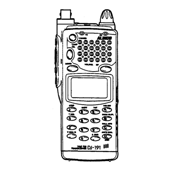
Alinco DJ-191 Manual de instrucciones - Página 12
Navegue en línea o descargue pdf Manual de instrucciones para Transceptor Alinco DJ-191. Alinco DJ-191 18 páginas. Cert communications team procedures
También para Alinco DJ-191: Manual de instrucciones (18 páginas), Referencia rápida (3 páginas), Referencia rápida (4 páginas)

III
8. GETTING STARTED
III
1'-/
1'-/6
1'-/6.5
1'-/6.52
18
@VOL
@SQL
@M
@88
@88888
@L
@CJ
@mmD
@ . (decimal
point)
@
icicicicicO
It appears while the volume level is being adjusted by either the
upward key or downward key.
It appears while the squelch level is being adjusted by pressing the
iii
key and either the upward key or downward key.
In the Memory Mode, the "M" icon appears.
In the VFO Mode, the "M" icon is not displayed.
While either the volume level or squelch level is adjusted, some
numbers will appear indicating the setting levels (min. O-max.
31).
In the Memory Mode, it indicates the selected memory channel
number (0 - 39, or "C" for call channel).
It indicates the transmit/receive frequency, offset frequency, tone
frequency, tuning step" DSQ code and AUTO DIAL code.
When the low power output is selected, the "L" icon appears.
When the "L" icon is not displayed, the high power output is
selected. (Not applicable for DJ-491C)
When the voltage of the battery is dropped and need to be
recharged, the "B" icon appears.
If it is displayed, turn off the power and recharge the battery. It will
take approximately 12 to 14 hours to be fully charged with EDC-63
or EDC-64.
The "BUSY" icon will appear when a signal is received, or
squelch is unmuted.
(During DSQ or TSQ, the audio remains muted unless the tones
match, regardless of the "BUSY" icon.)
It indicates: MHz for transmit/receive and offset frequencies.
kHz for channel step.
Hz for encoded sub-audible tone (CTCSS) tone
frequency.
In the Scan Mode, the decimal point flashes.
It indicates the received signal strength and/or the output power
level.
8-1 Receiving
1. Adjust the following and controls of the unit.
POWER SWITCH:
OFF
VOLUME CONTROL:
Set to "0" level
SQUELCH CONTROL: Set to "0" level
2. Connect a battery pack or external 4.8 - 13.8 Volt DC Regurated Power Supply to
the radio.
3. Ensure an antenna with the appropriate antenna connector is connected.
4. Turn the POWER switch on.
5. Press the upward key until a signal (or noise) is heard through the speaker.
6. The LCD display will indicate frequency.
7. Rotate the Main Tuning Dial, or enter the frequency from the DTMF keypad to select
a frequency. Press and hold the
iii
key, then press the upward key until the noise
disappears from the speaker.
KEYPAD DIRECT ENTRY
When a frequency is selected by the direct keypad entry, numbers will appear on the
LCD display as they are entered through each push of a key.
To enter a frequency directly from the keypad, perform the following.
The following example will use frequency 146.52MHz, and step of 5kHz.
1. Enter the 1OOMHz digit first. Example: 1_._
2. Enter the 10MHz digit next. Example: 14_._
3. Enter the
1MHz digit next. Example: 146._
4. Enter the 100kHz digit next. Example: 146.5_
5. Enter the 10kHz digit next. Example: 146.52_
6. Enter the
1kHz digit next. Example: 146.520
STEP KEY
The STEP function is used to select the desired incremental changes of receive/
transmit frequencies, in step of 5, 10, 12.5,15,20,25, 30kHz. Use this feature as
follows:
1. Enter the VFO MODE.
2. Press and hold the
iii
key, then press the
dS
key.
Change the channel step by using the Main Tuning Dial.
3. Press the PTT switch to return to the operating frequency.
4. After the channel step is set, the receive/transmit frequency will increase or
decrease by the value selected when you turn the Main Tuning Dial.
19
