Aqua DET 1 Manual de instrucciones - Página 6
Navegue en línea o descargue pdf Manual de instrucciones para Bomba de agua Aqua DET 1. Aqua DET 1 20 páginas.

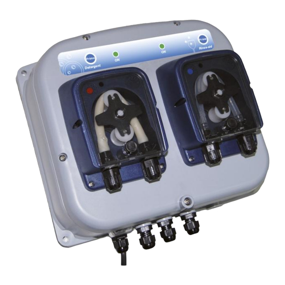
Rinse pump (DX pump)
Connect the PVC 4x6 hose (internal diameter 4 mm, external 6 mm) to the suction nipple (1).
Insert the foot filter to the other end of the hose.
Connect the PE 4x6 hose (internal diameter 4 mm, external 6 mm) to the delivery nipple (1).
Insert the Stainless Steel Rinse Injection fitting to the other end of the hose.
Tighten nuts (3 and 4) (see Fig.2).
To fix the pump to the wall use the screws supplied with the pump. Make 4 holes according to dimensions
shown in Fig. 3. Fix the bracket to the wall and then fit the pump to it. Try to keep both the suction and
discharge hose as straight as possible, avoiding any unnecessary bends. Install the pump away from direct
sources of heat and in a dry place at a maximum environment temperature of 40°C. The minimum operating
temperature depends on the liquid dosed and has to remain in a liquid state.
All electrical connections to the AQUA DET1 should first be verified with a meter. AQUA DET 1 is designed
to work with multi-voltage power supply from 24 VAC (set JP1 on B) to 230 VAC (set JP1 on A) 50/60 Hz.
Application of the incorrect voltage will permanently damage the unit and will not covered under the
warranty.
Electrical connection
It's possible to connect the system in two ways: Standard (configuration #1 – with just one cable) like now or
with a separated power supply (configuration #2 – with two cables) just in case of need.
In the dishwashing machine with the electronic control (relays output), we suggest to use the
configuration #2 with two cables.
Configuration #1 – (one cable "Standard")
WARNING: Always disconnect the power supply when servicing the unit
Connect the power supply cable to the dish-washing solenoid valve. When powered both peristaltic pumps
will run at the set flow-rate (set by trimmers inside, see layout circuit board). It is possible to fix a maximum
dosing time of 30 sec for the rinse pump using the DIP SWITCH (see DIP SWITCH USE TABLE).
As an option it could be connected to 2 level probes ADSLG1 on the circuit input. The low level alarm can be
also be used with a Buzzer (see DIP SWITCH USE TABLE).
Layout circuit board
ADSP7000430
07/05/2015
WALL MOUNTING (Fig. 3)
ELECTRIC CONNECTION (Fig. 4)
rev. 2.4
Configuration #2 – (two cables)
6/20
