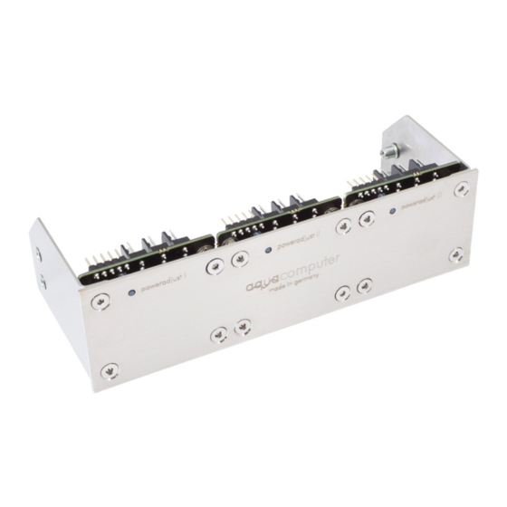
Aqua Computer poweradjust 3 Manual de uso e instalación - Página 14
Navegue en línea o descargue pdf Manual de uso e instalación para Controlador Aqua Computer poweradjust 3. Aqua Computer poweradjust 3 20 páginas. Usb unit is a high power fan or pump controller for pcs

aqua
computer
POWERADJUST 3
Select the desired mode of operation for the fan output below the diagram. If
"Manual fan settings" is selected, the fan output can be set to a fixed value. In
"Speed controlled" mode, you can set the desired rotation speed, the poweradjust
3 controller will regulate output power to keep the speed constant if technically
possible. In "Automatic temperature control" mode (Ultra version only), the fan
power will be dynamically adjusted depending on the current temperature sensor
reading.
9.2. Manual fan settings
9.2. Manual fan settings
9.2. Manual fan settings
9.2. Manual fan settings
When using manual mode, set the desired output power here.
9.3. Speed settings
9.3. Speed settings
9.3. Speed settings
9.3. Speed settings
When using the speed controlled mode, set the desired speed here. The controller
speed setting should not be changed in normal setups.
9.4. Automatic temperature control
9.4. Automatic temperature control
9.4. Automatic temperature control
9.4. Automatic temperature control
When using the automatic temperature control mode, set the desired target tem-
perature. The controller speed setting should not be changed in normal setups.
9.5. Start boost and output settings
9.5. Start boost and output settings
9.5. Start boost and output settings
9.5. Start boost and output settings
The start boost feature can be used to reliably power up a fan or pump connected
to the power output. If activated, the poweradjust 3 unit will set the output to the
configured power for the configured duration before switching to normal opera-
tion. Exception: If the power output is set to 0 % (either by manual setting or by au-
tomatic control), the start boost will not be activated even if speed signal and/or
flow signal should be missing. If this behavior is not suitable for your application,
make sure to use the "Hold minimum power" feature described in the next para-
graph!
When using the speed controlled mode or the automatic temperature control
mode, the output range can be limited in both directions ("Minimum
power"/"Maximum power"). The check box "Hold minimum power" determines
whether the output will be switched off for low temperature sensor readings (box
not checked) or remain active at the set minimum power/speed (box checked). Set
minimum power to a value at which the connected fan or pump reliably starts up.
10. Alarm configuration(aquasuite)
10. Alarm configuration(aquasuite)
10. Alarm configuration(aquasuite)
10. Alarm configuration(aquasuite)
Select "Alarm configuration" from the device list for the device to be configured.
10.1. Speed signal/Output
10.1. Speed signal/Output
10.1. Speed signal/Output
10.1. Speed signal/Output
Select the signal to be provided through the speed signal output. Available options
are the speed signal of a connected fan/pump or flow sensor or an artificial speed
- 14 -
Aqua Computer GmbH & Co. KG
© 2014-2016
Gelliehäuser Str. 1, 37130 Gleichen
