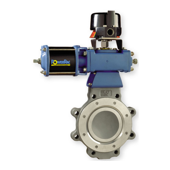
DeZurik D10350 Manual de inicio rápido - Página 4
Navegue en línea o descargue pdf Manual de inicio rápido para Transmisor DeZurik D10350. DeZurik D10350 9 páginas. Switch and positioner transmitter

DeZURIK
Description
This valve accessory provides electrical functions in response to the open, closed, and intermediate
positions of a 2-way valve or a 2-position 3-way valve. Electrical switching and variable current
functions are provided in selected combinations. The adjustable sensing devices are mechanically
linked to a valve, a valve actuator, or a positioner.
Components are located in a sealed and accessible aluminum enclosure, constructed to comply with
NEMA types 4, 4X, 7 and 9. The position of the valve is visibly displayed in two windows at 180°
viewing angles. Three basic options consisting of mechanical switches, proximity switches, and a
position transmitter are provided individually or in selected combinations. The three options are
described below.
Electrical Connections
Field wiring enters through ¾" and ½" NPT electrical connections to a prewired and labeled terminal
strip as described in the following sections. One ½" pipe plug is provided with the unit. If the ½"
connection is not used, install the pipe plug tightly in the connection. Do not use thread sealant.
Mechanical Switches
The two SPDT or four SPDT mechanical snap-acting switches each have a rating of:
Silver Contacts -10 Amps at 125/250 VAC, or 0.5 Amp at 125 VDC.
Gold Contacts - 1 Amp at 125 VAC, or 0.5 Amp at 30 VDC
With two SPDT switches, the top switch is factory set to trip as the valve reaches the closed or
clockwise position, and the bottom switch is factory set to trip as the valve reaches the open or counter-
clockwise position. The internal wiring from the switches to the terminal strip is shown in Figure 1.
With four SPDT switches, the top (first) switch is factory set to trip as the valve reaches the closed or
clockwise position, and the bottom (fourth) switch is factory set to trip as the valve reaches the open or
counterclockwise position. The second and third switches are not factory set, but may be set in the
field. The internal wiring from the switches to the terminal strip is shown in Figure 2.
D10350
Figure 1— Mechanical Switches
Page 4
May 2014
