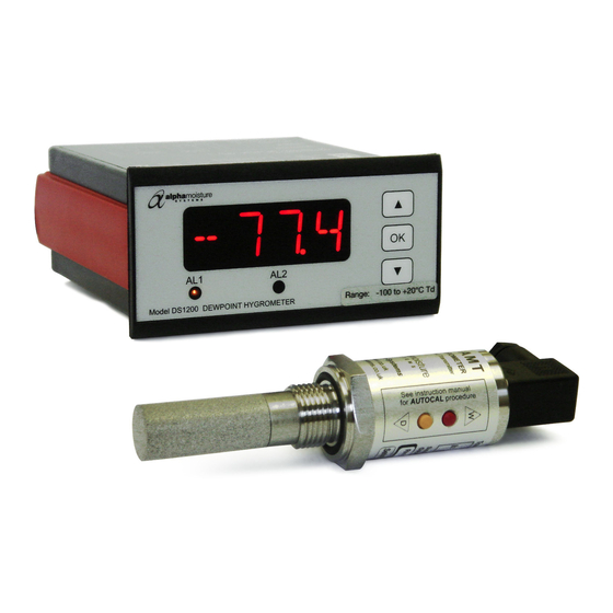
Alpha Moisture Systems DS1200-AMT Manual de instalación, puesta en marcha y funcionamiento - Página 7
Navegue en línea o descargue pdf Manual de instalación, puesta en marcha y funcionamiento para Instrumentos de medida Alpha Moisture Systems DS1200-AMT. Alpha Moisture Systems DS1200-AMT 18 páginas. Dewpoint analysis system

Rs max = [40 x (Vs – 7) ]Ω.
If the wiring resistance is expected to be more than a few percent of the value of Rs, then this resistance
must be taken away from the answer to get the maximum usable value of Rs.
4.7
Connector Pins
5 Gas Compatibilities
The Model AMT sensing elements are Al
research applications. Most gases can be checked for their moisture content with no need for the
calibration to be altered when changing between different gases, as the sensor operates only with
reference to the water vapour content.
compatible with the material used in the construction of the sensor. Ammonia (NH3) and chlorine (Cl)
must be avoided at all times, even in small quantities. Hydrogen chloride (HCl) also attacks the sensors
very quickly. Some, less aggressive, acidic gases, such as sulphur dioxide (SO2), can be monitored, as
long as the moisture content is low, generally less than 100ppm(v). If in doubt, please ask your supplier.
Sulphur hexaflouride (SF
is possible that various acidic species will have been formed that will corrode the sensor. When testing
SF
that may have been arced, therefore, an acidity test should be carried out first; if the gas proves to be
6
acidic then the moisture test should not be carried out.
It is strongly recommended that the sample should not contain particulate matter, oil or other heavy
hydrocarbon condensate. If these components contaminate the sample system and/or the measuring
sensor, the system response time will be lengthened, although the sensor calibration will not be
effected.
6 Installing in the Air/Gas Sampling system
•
The piping installation schematic diagram below shows all components which could be used in a dry
gas measurement application although all the items shown will not be required for every installation.
•
The flow rate, although not critical to the sensor measurement, should be low enough to avoid
abrasion to the sensor surface without being so low as to extend the system response time to an
unacceptable level. In general, a flow rate of between 2 and 3 litres/min at NTP will give the right
balance.
•
The sensor is a variable capacitor which is directly affected by changes in partial pressure of water
vapour and these changes, which are proportional to the dew/frost point temperature, are displayed on
the instrument indicator.
•
Partial pressure of water vapour is directly affected by total pressure and, this being the case, the
instrument will display the dew/frost point temperature at whatever total pressure the sensor is
exposed, therefore care should be taken to ensure that the sample pressure, at the sensor is that at
which the dew/frost point readings are required.
Red = 12 to 28V dc Power Supply
O
and therefore suitable for many different industrial and
2
3
However, some gases must be avoided, as they are not
) has no effect on the sensor. If the gas has been exposed to arcing, however, it
6
Page 4
Blue = 4-20mA Current Return
