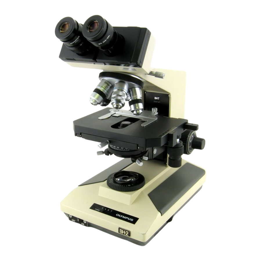
Olympus BH2 Series Desmontaje, limpieza y montaje completos - Página 4
Navegue en línea o descargue pdf Desmontaje, limpieza y montaje completos para Microscopio Olympus BH2 Series. Olympus BH2 Series 40 páginas. Phase contrast
También para Olympus BH2 Series: Manual de solución de problemas y ajuste (46 páginas), Desmontaje, limpieza y montaje completos (23 páginas), Desmontaje, limpieza y montaje (45 páginas), Manual (6 páginas), Manual de instalación (9 páginas)

Figure 13 - Remove the caps from the fine-focus knobs ..................................................................................................... 11
Figure 14 - Insert Allen drivers into screws in both knobs ................................................................................................... 12
Figure 15 - Remove fine-focus knob from shaft (left side) .................................................................................................. 12
Figure 16 - Plastic gear in the right-hand fine-focus knob ................................................................................................... 12
Figure 17 - Withdraw the fine-focus shaft (right side) ......................................................................................................... 12
Figure 18 - A view of the fine-focus gear cluster ................................................................................................................. 13
Figure 19 - A view of the fine-focus thrust washers ............................................................................................................ 13
Figure 20 - Remove the nylon thrust washer ....................................................................................................................... 13
Figure 21 - Remove screws holding the coarse-focus knob ................................................................................................. 13
Figure 22 - Remove the left-hand coarse-focus knob .......................................................................................................... 14
Figure 23 - Remove the stop screw for the lock collar ......................................................................................................... 14
Figure 24 - Loosen setscrews holding brass shaft mount .................................................................................................... 14
Figure 25 - Hold the brass shaft mount stationary .............................................................................................................. 14
Figure 26 - The loose brass shaft mount .............................................................................................................................. 15
Figure 27 - Spring and washer under brass shaft mount ..................................................................................................... 15
Figure 28 - Loosen and remove the pre-focus lock collar .................................................................................................... 15
Figure 29 - Remove the nylon thrust washer ....................................................................................................................... 15
Figure 30 - Remove the rotating lock ring ............................................................................................................................ 15
Figure 31 - Remove screws holding the threaded lock ring ................................................................................................. 16
Figure 32 - Remove threaded lock ring from pillar arm ....................................................................................................... 16
Figure 33 - The fine-focus gear cluster ................................................................................................................................. 16
Figure 34 - Remove screws holding gear-retaining ring ....................................................................................................... 16
Figure 35 - Remove the brass gear-retaining ring ................................................................................................................ 16
Figure 36 - The gear-retaining ring has been removed ........................................................................................................ 17
Figure 37 - Remove the top (right-most) drive gear ............................................................................................................ 17
Figure 38 - Remove the middle drive gear ........................................................................................................................... 17
Figure 39 - Remove the bottom (left-most) gear ................................................................................................................. 17
Figure 40 - Rear view of the right-hand coarse-focus knob ................................................................................................. 17
Figure 41 - Grease lower pin of bottom (left-most) gear ..................................................................................................... 18
Figure 42 - Place bottom (left-most) drive gear in position ................................................................................................. 18
Figure 43 - Grease the lower pin of the middle gear ........................................................................................................... 18
Figure 44 - Place the middle drive gear in position .............................................................................................................. 18
Figure 45 - Grease lower pin of top (right-most) drive gear ................................................................................................ 18
Figure 46 - Place top (right-hand) drive gear in position ..................................................................................................... 18
Figure 47 - Grease the top pins of all three gears ................................................................................................................ 19
Figure 48 - Gear-retaining ring in position over the gears ................................................................................................... 19
Figure 49 - Reinstall screws to secure gear-retaining ring ................................................................................................... 19
Figure 50 - Withdraw the coarse-focus shaft from pinion ................................................................................................... 19
Figure 51 - Loosen setscrews holding the pinion assembly ................................................................................................. 20
Figure 52 - Withdraw pinion assembly from the pillar arm ................................................................................................. 20
Figure 53 - Unscrew the tension-adjustment knob ............................................................................................................. 20
Figure 54 - Remove the nylon tension washer ..................................................................................................................... 20
Figure 55 - Remove the metal wave tension washer ........................................................................................................... 21
Figure 56 - Heat the slotted brass retaining ring ................................................................................................................. 21
Figure 57 - Grip the gear end with non-marring pliers ........................................................................................................ 21
Figure 58 - Remove the slotted brass retaining ring ............................................................................................................ 21
Figure 59 - Bearing balls in the retaining-ring end ............................................................................................................... 21
Figure 60 - Bearing balls removed from retaining-ring end ................................................................................................. 22
Figure 61 - The bearing balls removed from gear end ......................................................................................................... 22
Complete Teardown, Cleaning, and Reassembly of the Olympus BH-2 Coaxial Focus Mechanism
Revision 4
Page 4 of 40
