Olympus BH2 Series Pembongkaran, Pembersihan, dan Pemasangan Kembali Lengkap - Halaman 4

Jelajahi secara online atau unduh pdf Pembongkaran, Pembersihan, dan Pemasangan Kembali Lengkap untuk Mikroskop Olympus BH2 Series. Olympus BH2 Series 40 halaman. Phase contrast
Juga untuk Olympus BH2 Series: Panduan Pemecahan Masalah & Penyesuaian (46 halaman), Pembongkaran, Pembersihan, dan Pemasangan Kembali Lengkap (23 halaman), Pembongkaran, Pembersihan, dan Pemasangan Kembali (45 halaman), Manual (6 halaman), Panduan Instalasi (9 halaman)
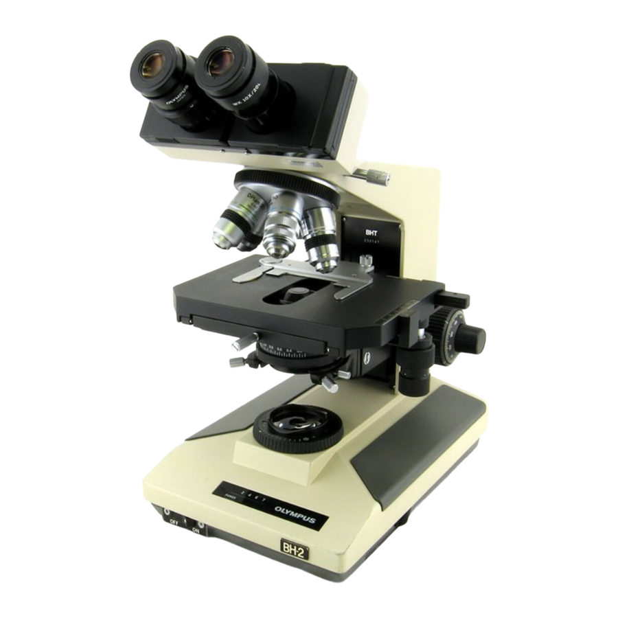
Olympus BH2 Series Pembongkaran, Pembersihan, dan Pemasangan Kembali Lengkap
Figure 13 - Remove the caps from the fine-focus knobs ..................................................................................................... 11
Figure 14 - Insert Allen drivers into screws in both knobs ................................................................................................... 12
Figure 15 - Remove fine-focus knob from shaft (left side) .................................................................................................. 12
Figure 16 - Plastic gear in the right-hand fine-focus knob ................................................................................................... 12
Figure 17 - Withdraw the fine-focus shaft (right side) ......................................................................................................... 12
Figure 18 - A view of the fine-focus gear cluster ................................................................................................................. 13
Figure 19 - A view of the fine-focus thrust washers ............................................................................................................ 13
Figure 20 - Remove the nylon thrust washer ....................................................................................................................... 13
Figure 21 - Remove screws holding the coarse-focus knob ................................................................................................. 13
Figure 22 - Remove the left-hand coarse-focus knob .......................................................................................................... 14
Figure 23 - Remove the stop screw for the lock collar ......................................................................................................... 14
Figure 24 - Loosen setscrews holding brass shaft mount .................................................................................................... 14
Figure 25 - Hold the brass shaft mount stationary .............................................................................................................. 14
Figure 26 - The loose brass shaft mount .............................................................................................................................. 15
Figure 27 - Spring and washer under brass shaft mount ..................................................................................................... 15
Figure 28 - Loosen and remove the pre-focus lock collar .................................................................................................... 15
Figure 29 - Remove the nylon thrust washer ....................................................................................................................... 15
Figure 30 - Remove the rotating lock ring ............................................................................................................................ 15
Figure 31 - Remove screws holding the threaded lock ring ................................................................................................. 16
Figure 32 - Remove threaded lock ring from pillar arm ....................................................................................................... 16
Figure 33 - The fine-focus gear cluster ................................................................................................................................. 16
Figure 34 - Remove screws holding gear-retaining ring ....................................................................................................... 16
Figure 35 - Remove the brass gear-retaining ring ................................................................................................................ 16
Figure 36 - The gear-retaining ring has been removed ........................................................................................................ 17
Figure 37 - Remove the top (right-most) drive gear ............................................................................................................ 17
Figure 38 - Remove the middle drive gear ........................................................................................................................... 17
Figure 39 - Remove the bottom (left-most) gear ................................................................................................................. 17
Figure 40 - Rear view of the right-hand coarse-focus knob ................................................................................................. 17
Figure 41 - Grease lower pin of bottom (left-most) gear ..................................................................................................... 18
Figure 42 - Place bottom (left-most) drive gear in position ................................................................................................. 18
Figure 43 - Grease the lower pin of the middle gear ........................................................................................................... 18
Figure 44 - Place the middle drive gear in position .............................................................................................................. 18
Figure 45 - Grease lower pin of top (right-most) drive gear ................................................................................................ 18
Figure 46 - Place top (right-hand) drive gear in position ..................................................................................................... 18
Figure 47 - Grease the top pins of all three gears ................................................................................................................ 19
Figure 48 - Gear-retaining ring in position over the gears ................................................................................................... 19
Figure 49 - Reinstall screws to secure gear-retaining ring ................................................................................................... 19
Figure 50 - Withdraw the coarse-focus shaft from pinion ................................................................................................... 19
Figure 51 - Loosen setscrews holding the pinion assembly ................................................................................................. 20
Figure 52 - Withdraw pinion assembly from the pillar arm ................................................................................................. 20
Figure 53 - Unscrew the tension-adjustment knob ............................................................................................................. 20
Figure 54 - Remove the nylon tension washer ..................................................................................................................... 20
Figure 55 - Remove the metal wave tension washer ........................................................................................................... 21
Figure 56 - Heat the slotted brass retaining ring ................................................................................................................. 21
Figure 57 - Grip the gear end with non-marring pliers ........................................................................................................ 21
Figure 58 - Remove the slotted brass retaining ring ............................................................................................................ 21
Figure 59 - Bearing balls in the retaining-ring end ............................................................................................................... 21
Figure 60 - Bearing balls removed from retaining-ring end ................................................................................................. 22
Figure 61 - The bearing balls removed from gear end ......................................................................................................... 22
Complete Teardown, Cleaning, and Reassembly of the Olympus BH-2 Coaxial Focus Mechanism
Revision 4
Page 4 of 40