Olympus BH2 Series Pembongkaran, Pembersihan, dan Pemasangan Kembali Lengkap - Halaman 5

Jelajahi secara online atau unduh pdf Pembongkaran, Pembersihan, dan Pemasangan Kembali Lengkap untuk Mikroskop Olympus BH2 Series. Olympus BH2 Series 40 halaman. Phase contrast
Juga untuk Olympus BH2 Series: Panduan Pemecahan Masalah & Penyesuaian (46 halaman), Pembongkaran, Pembersihan, dan Pemasangan Kembali Lengkap (23 halaman), Pembongkaran, Pembersihan, dan Pemasangan Kembali (45 halaman), Manual (6 halaman), Panduan Instalasi (9 halaman)
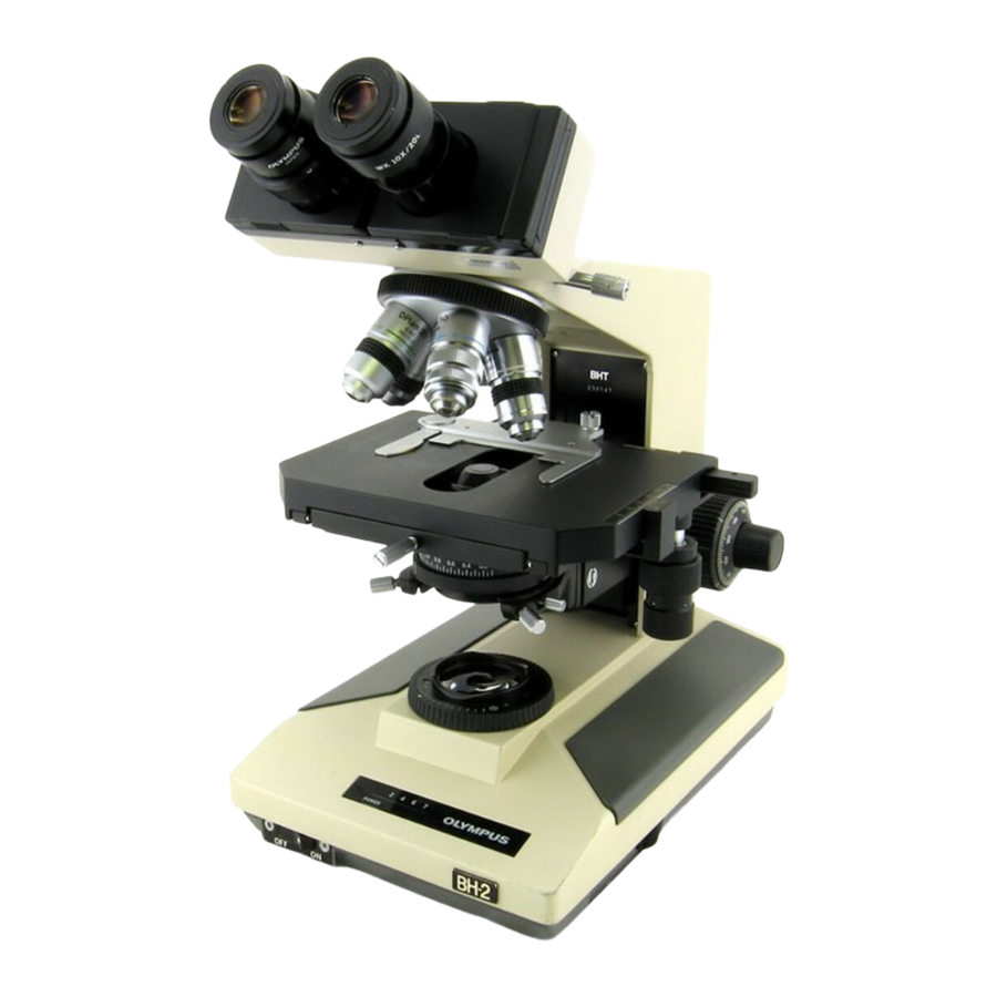
Olympus BH2 Series Pembongkaran, Pembersihan, dan Pemasangan Kembali Lengkap
Figure 62 - Apply grease to upper face of the pinion gear ................................................................................................... 22
Figure 63 - Bearing balls on the top face of the gear ........................................................................................................... 22
Figure 64 - Lower brass pinion mount over steel pinion ..................................................................................................... 22
Figure 65 - Apply ring of grease to the retaining-ring end ................................................................................................... 23
Figure 66 - Place bearing balls in the retaining-ring end ..................................................................................................... 23
Figure 67 - Reinstall the slotted brass retaining ring ........................................................................................................... 23
Figure 68 - Reinstall the greased metal wave washer.......................................................................................................... 23
Figure 69 - Reinstall the greased nylon tension washer ...................................................................................................... 24
Figure 70 - Reinstall the tension-adjustment knob .............................................................................................................. 24
Figure 71 - Snug the tension-adjustment knob .................................................................................................................... 24
Figure 72 - Slide the pinion assembly into the pillar arm .................................................................................................... 24
Figure 73 - A view of the indexing holes in the pinion mount ............................................................................................. 24
Figure 74 - Start both setscrews into pillar arm casting ...................................................................................................... 25
Figure 75 - Apply Loctite® before tightening setscrews ....................................................................................................... 25
Figure 76 - Apply Loctite® to secure the retaining ring ........................................................................................................ 25
Figure 77 - Apply grease to the bearing surface .................................................................................................................. 25
Figure 78 - Slide coarse-focus shaft into the hollow pinion ................................................................................................. 25
Figure 79 - Reinstall the threaded lock ring ......................................................................................................................... 26
Figure 80 - Reinstall the rotating lock ring ........................................................................................................................... 26
Figure 81 - Lightly grease threads of threaded lock ring ...................................................................................................... 26
Figure 82 - Reinstall the pre-focus lock collar ...................................................................................................................... 26
Figure 83 - Reinstall nylon washer onto end of pinion mount ............................................................................................. 27
Figure 84 - Place the rear loop of spring over stop screw.................................................................................................... 27
Figure 85 - Place front loop of the spring over stop screw .................................................................................................. 27
Figure 86 - Reinstall setscrews to lock brass shaft mount ................................................................................................... 28
Figure 87 - Reinstall slotted stop screw for the lock collar .................................................................................................. 29
Figure 88 - Reinstall the left-hand coarse-focus knob ......................................................................................................... 29
Figure 89 - Reinstall nylon washer onto the shaft mount .................................................................................................... 29
Figure 90 - Reinstall spring washer over the nylon washer ................................................................................................. 29
Figure 91 - Slide fine-focus shaft into coarse-focus shaft .................................................................................................... 30
Figure 92 - Reinstall the fine-focus knob (left side shown) .................................................................................................. 30
Figure 93 - Reinstall screw to secure the second knob ........................................................................................................ 30
Figure 94 - Reinstall the top screw to hang the focus rack .................................................................................................. 30
Figure 95 - Reinstall the lower screw for the focus rack ...................................................................................................... 31
Figure 96 - Grease the teeth of the focus rack (optional) .................................................................................................... 31
Figure 97 - Remove two setscrews securing the gears ........................................................................................................ 31
Figure 98 - Press both gear pins free of the housing ........................................................................................................... 31
Figure 99 - The fully disassembled focus gearbox................................................................................................................ 32
Figure 100 - Washer and pin ready to receive the first gear ............................................................................................... 32
Figure 101 - The first gear held in place by the gear pin ...................................................................................................... 32
Figure 102 - Insert nylon washer on opposite side of pin .................................................................................................... 32
Figure 103 - Gear pin and first gear in final position ............................................................................................................ 33
Figure 104 - Washer and pin ready to receive second gear ................................................................................................. 33
Figure 105 - The second gear held in place by the gear pin ................................................................................................. 33
Figure 106 - Insert nylon washer on opposite side of pin .................................................................................................... 33
Figure 107 - Gear pins holding both gears ........................................................................................................................... 34
Figure 108 - Reinstall two setscrews to secure the gears .................................................................................................... 34
Figure 109 - Apply grease to the teeth of both gears .......................................................................................................... 34
Figure 110 - Stick shims onto flanges with dabs of grease .................................................................................................. 34
Complete Teardown, Cleaning, and Reassembly of the Olympus BH-2 Coaxial Focus Mechanism
Revision 4
Page 5 of 40