Siemens SINAMICS G120 Primeros pasos - Página 23

Navegue en línea o descargue pdf Primeros pasos para Equipamiento industrial Siemens SINAMICS G120. Siemens SINAMICS G120 50 páginas. Using blocksize converters in marine applications
También para Siemens SINAMICS G120: Primeros pasos (46 páginas), Manual de instrucciones (32 páginas), Primeros pasos (30 páginas), Instrucciones de instalación del hardware (2 páginas), Instrucciones de instalación y manual del usuario (2 páginas), Instrucciones de instalación (2 páginas), Instrucciones de instalación (2 páginas), Instrucciones de uso Compact (32 páginas), Manual (42 páginas), Manual del dispositivo (34 páginas), Manual de instalación rápida (2 páginas), Descripción de la aplicación (50 páginas), Instrucciones de uso Compact (2 páginas), Manual (31 páginas), Manual de aplicaciones (34 páginas), Instrucciones de uso Compact (2 páginas), Instrucciones de uso Compact (2 páginas)
Siemens SINAMICS G120 Primeros pasos
The factory settings described above for USS and PROFIBUS/PROFINET terminals
correspond to default setting 12 (two-wire control using method 1) or default setting 7
(switchover between fieldbus and jog using DI 3).
See also: Default settings of the terminal strip (Page 28).
3.3.2

CU240B / CU240E Control Unit

3.3.2.1

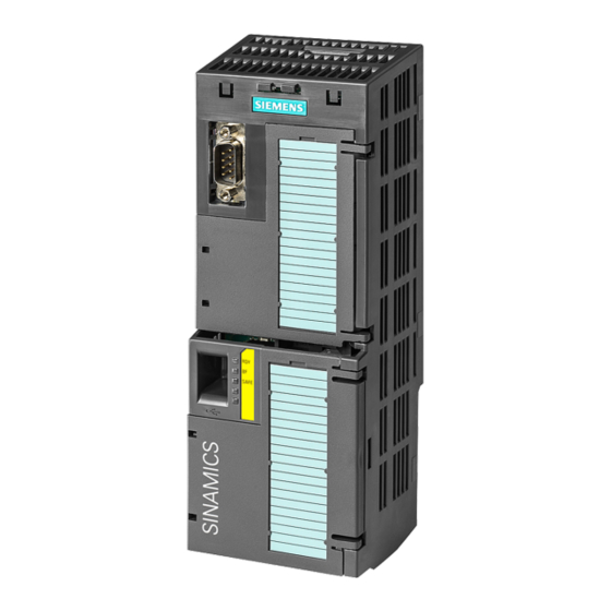
Interfaces at the front of the CU240B-2 and CU240E-2

Interfaces at the front of the Control Unit
To access the interfaces at the front of the Control Unit, you must lift the Operator Panel (if
one is being used) and open the front doors.
Converter with Control Units CU230P-2; CU240B-2; CU240E-2
Getting Started, 04/2014, A5E32885834B AB
Memory card slot
Terminal strips
Depending on the fieldbus:
• USS, Modbus: Bus
termination
• PROFIBUS, PROFINET,
EtherNet/IP: No function
Fieldbus interfaces at the lower side
Selecting the fieldbus address:
• CU230P-2 DP
• CU230P-2 CAN
• CU230P-2 HVAC
• CU230P-2 BT
Terminal strips for the digital outputs
Status LED
USB interface for connection to a PC
Switch for AI0 and AI1 (U/I)
• I
0/4 mA ... 20 mA
• U -10/0 V ... 10 V
Connection to the operator panel
Installing
3.3 Installing Control Unit
23