Siemens SINAMICS G120 Початок роботи - Сторінка 23

Переглянути онлайн або завантажити pdf Початок роботи для Промислове обладнання Siemens SINAMICS G120. Siemens SINAMICS G120 50 сторінок. Using blocksize converters in marine applications
Також для Siemens SINAMICS G120: Початок роботи (46 сторінок), Інструкція з експлуатації Посібник з експлуатації (32 сторінок), Початок роботи (30 сторінок), Інструкція з встановлення обладнання (2 сторінок), Інструкція з монтажу та посібник користувача (2 сторінок), Інструкція з монтажу (2 сторінок), Інструкція з монтажу (2 сторінок), Компактна інструкція з експлуатації (32 сторінок), Посібник (42 сторінок), Посібник з експлуатації пристрою (34 сторінок), Посібник зі швидкого встановлення (2 сторінок), Опис програми (50 сторінок), Компактна інструкція з експлуатації (2 сторінок), Посібник (31 сторінок), Посібник із застосування (34 сторінок), Компактна інструкція з експлуатації (2 сторінок), Компактна інструкція з експлуатації (2 сторінок)
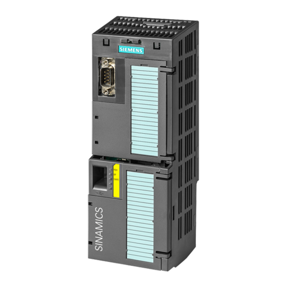
Siemens SINAMICS G120 Початок роботи
The factory settings described above for USS and PROFIBUS/PROFINET terminals
correspond to default setting 12 (two-wire control using method 1) or default setting 7
(switchover between fieldbus and jog using DI 3).
See also: Default settings of the terminal strip (Page 28).
3.3.2

CU240B / CU240E Control Unit

3.3.2.1

Interfaces at the front of the CU240B-2 and CU240E-2

Interfaces at the front of the Control Unit
To access the interfaces at the front of the Control Unit, you must lift the Operator Panel (if
one is being used) and open the front doors.
Converter with Control Units CU230P-2; CU240B-2; CU240E-2
Getting Started, 04/2014, A5E32885834B AB
Memory card slot
Terminal strips
Depending on the fieldbus:
• USS, Modbus: Bus
termination
• PROFIBUS, PROFINET,
EtherNet/IP: No function
Fieldbus interfaces at the lower side
Selecting the fieldbus address:
• CU230P-2 DP
• CU230P-2 CAN
• CU230P-2 HVAC
• CU230P-2 BT
Terminal strips for the digital outputs
Status LED
USB interface for connection to a PC
Switch for AI0 and AI1 (U/I)
• I
0/4 mA ... 20 mA
• U -10/0 V ... 10 V
Connection to the operator panel
Installing
3.3 Installing Control Unit
23