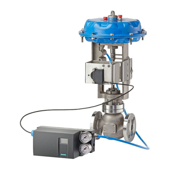
Electropneumatic positioners
SIPART PS2
Technical specifications
SIPART PS2
SIPART PS2
3-/4-wire device (terminals 2/4
and 6/8) (6DR52.. and 6DR53..)
• Power supply U
H
• Current consumption I
• Internal capacitance C
• Internal inductance L
For connection to power circuits with
the following max. ratings
Current input I
W
Rated signal range
Load voltage at 20 mA
Internal capacitance C
Internal inductance (L
For connection to power circuits with
the following max. ratings
6
Electrical isolation
Test voltage
Connections
• Electric
• Pneumatic
External position sensor (potentiometer or NCS; as option) with the following max. ratings
• U
o
• Io (static)
• I
(short-time)
s
• P
o
Maximum permissible external capaci-
tance C
o
Maximum permissible external induc-
tance L
o
6/10
Siemens FI 01 · 2009
Basic device
without Ex protection
18 ... 35 V DC
(U
- 7.5 V)/2.4 kΩ [mA]
H
H
–
i
–
i
–
0/4 ... 20 mA
≤ 0.2 V (corresponds to
10 Ω)
–
i
)
–
i
–
between U
and I
H
840 V DC (1 s)
Screw terminals 2.5
AWG28-12
Cable gland M20 x 1.5 or
½-14 NPT
Female thread G¼ DIN
EN ISO 228-1 or ¼-18
NPT
–
–
–
–
–
–
© Siemens AG 2008
Basic device
with Ex d protection
(flameproof casing)
18 ... 35 V DC
(U
- 7.5 V)/2.4 kΩ [mA]
H
–
–
–
0/4 ... 20 mA
≤ 0.2 V (corresponds to
10 Ω)
–
–
–
between U
and I
W
H
W
840 V DC (1 s)
Screw terminals 2.5
AWG28-12
EEx d certified cable
gland M20 x 1.5,
½-14 NPT or M25 x 1.5
Female thread G¼ DIN
EN ISO 228-1 or ¼-18
NPT
–
–
–
–
–
–
Basic device
Basic device
with Ex ia/ib protection
with Ex n/dust protec-
tion
18 ... 30 V DC
18 ... 30 V DC
(U
- 7.5 V)/2.4 kΩ [mA]
(U
- 7.5 V)/2.4 kΩ [mA]
H
H
≤ 22 nF
–
≤ 0.12 mH
–
intrinsically safe
Un = 30 V DC
Ui = 30 V DC
In = 100 mA
Ii = 100 mA
at "nL":
Pi = 1 W
Ui = 30 V DC
Ii = 100 mA
0/4 ... 20 mA
0/4 ... 20 mA
≤ 1 V (corresponds to
≤ 1 V (corresponds to
50 Ω)
50 Ω)
22 nF
22 nF (at "nL")
0.12 mH
0.12 mH (at "nL")
intrinsically safe
at "nA" and "tD":
Ui = 30 V DC
Un = 30 V DC
Ii = 100 mA
In = 100 mA
Pi = 1 W
at "nL":
Ui = 30 V DC
Ii = 100 mA
between U
and I
between U
H
W
(2 intrinsically safe cir-
cuits)
840 V DC (1 s)
840 V DC (1 s)
Screw terminals 2.5
Screw terminals 2.5
AWG28-12
AWG28-12
Cable gland M20 x 1.5 or
Cable gland M20 x 1.5 or
½-14 NPT
½-14 NPT
Female thread G¼ DIN
Female thread G¼ DIN
EN ISO 228-1 or ¼-18
EN ISO 228-1 or ¼-18
NPT
NPT
5 V
5 V
75 mA
75 mA
160 mA
-
120 mW
120 mW
1 μF
1 μF
1 mH
1 mH
and I
H
W

