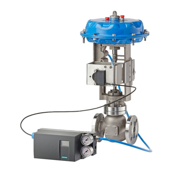
Siemens SIPART PS2 기술 설명 - 페이지 10
{카테고리_이름} Siemens SIPART PS2에 대한 기술 설명을 온라인으로 검색하거나 PDF를 다운로드하세요. Siemens SIPART PS2 26 페이지. Mounting bracket kit
Siemens SIPART PS2에 대해서도 마찬가지입니다: 설치 지침 (4 페이지), 사용 설명서 (28 페이지), 설치 지침 (4 페이지), 하드웨어 설치 매뉴얼 (30 페이지), 간결한 사용 설명서 (35 페이지), 키트 설치 지침 (9 페이지), 설치 지침 (11 페이지)

Electropneumatic positioners
SIPART PS2
Technical specifications
SIPART PS2
SIPART PS2
3-/4-wire device (terminals 2/4
and 6/8) (6DR52.. and 6DR53..)
• Power supply U
H
• Current consumption I
• Internal capacitance C
• Internal inductance L
For connection to power circuits with
the following max. ratings
Current input I
W
Rated signal range
Load voltage at 20 mA
Internal capacitance C
Internal inductance (L
For connection to power circuits with
the following max. ratings
6
Electrical isolation
Test voltage
Connections
• Electric
• Pneumatic
External position sensor (potentiometer or NCS; as option) with the following max. ratings
• U
o
• Io (static)
• I
(short-time)
s
• P
o
Maximum permissible external capaci-
tance C
o
Maximum permissible external induc-
tance L
o
6/10
Siemens FI 01 · 2009
Basic device
without Ex protection
18 ... 35 V DC
(U
- 7.5 V)/2.4 kΩ [mA]
H
H
–
i
–
i
–
0/4 ... 20 mA
≤ 0.2 V (corresponds to
10 Ω)
–
i
)
–
i
–
between U
and I
H
840 V DC (1 s)
Screw terminals 2.5
AWG28-12
Cable gland M20 x 1.5 or
½-14 NPT
Female thread G¼ DIN
EN ISO 228-1 or ¼-18
NPT
–
–
–
–
–
–
© Siemens AG 2008
Basic device
with Ex d protection
(flameproof casing)
18 ... 35 V DC
(U
- 7.5 V)/2.4 kΩ [mA]
H
–
–
–
0/4 ... 20 mA
≤ 0.2 V (corresponds to
10 Ω)
–
–
–
between U
and I
W
H
W
840 V DC (1 s)
Screw terminals 2.5
AWG28-12
EEx d certified cable
gland M20 x 1.5,
½-14 NPT or M25 x 1.5
Female thread G¼ DIN
EN ISO 228-1 or ¼-18
NPT
–
–
–
–
–
–
Basic device
Basic device
with Ex ia/ib protection
with Ex n/dust protec-
tion
18 ... 30 V DC
18 ... 30 V DC
(U
- 7.5 V)/2.4 kΩ [mA]
(U
- 7.5 V)/2.4 kΩ [mA]
H
H
≤ 22 nF
–
≤ 0.12 mH
–
intrinsically safe
Un = 30 V DC
Ui = 30 V DC
In = 100 mA
Ii = 100 mA
at "nL":
Pi = 1 W
Ui = 30 V DC
Ii = 100 mA
0/4 ... 20 mA
0/4 ... 20 mA
≤ 1 V (corresponds to
≤ 1 V (corresponds to
50 Ω)
50 Ω)
22 nF
22 nF (at "nL")
0.12 mH
0.12 mH (at "nL")
intrinsically safe
at "nA" and "tD":
Ui = 30 V DC
Un = 30 V DC
Ii = 100 mA
In = 100 mA
Pi = 1 W
at "nL":
Ui = 30 V DC
Ii = 100 mA
between U
and I
between U
H
W
(2 intrinsically safe cir-
cuits)
840 V DC (1 s)
840 V DC (1 s)
Screw terminals 2.5
Screw terminals 2.5
AWG28-12
AWG28-12
Cable gland M20 x 1.5 or
Cable gland M20 x 1.5 or
½-14 NPT
½-14 NPT
Female thread G¼ DIN
Female thread G¼ DIN
EN ISO 228-1 or ¼-18
EN ISO 228-1 or ¼-18
NPT
NPT
5 V
5 V
75 mA
75 mA
160 mA
-
120 mW
120 mW
1 μF
1 μF
1 mH
1 mH
and I
H
W
