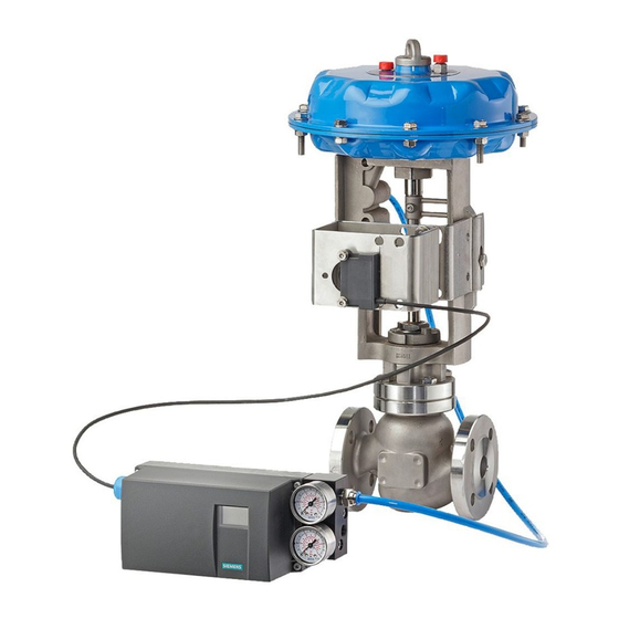
Siemens SIPART PS2 기술 설명 - 페이지 8
{카테고리_이름} Siemens SIPART PS2에 대한 기술 설명을 온라인으로 검색하거나 PDF를 다운로드하세요. Siemens SIPART PS2 26 페이지. Mounting bracket kit
Siemens SIPART PS2에 대해서도 마찬가지입니다: 설치 지침 (4 페이지), 사용 설명서 (28 페이지), 설치 지침 (4 페이지), 하드웨어 설치 매뉴얼 (30 페이지), 간결한 사용 설명서 (35 페이지), 키트 설치 지침 (9 페이지), 설치 지침 (11 페이지)

Electropneumatic positioners
SIPART PS2
Technical specifications
all versions
■
Technical specifications
SIPART PS2 (all versions)
General data
Travel range (linear actuators)
Angle of rotation
(part-turn actuators)
Installation
• On linear actuators
• On part-turn actuators
Controller
• Five-point switch
• Dead zone
- dEbA = Auto
- dEbA = 0.1 ... 10%
6
A/D converter
• Scan time
• Resolution
• Transmission error
• Temperature effect
Cycle time
• 20 mA/HART device
• PA device
• FF device
Binary input BE1 (terminals 9/10;
electrically connected to the basic
device)
Degree of protection
CE marking
EMC requirements
Material
• Housing
- 6DR5..0-... (plastic)
- 6DR5..1-... (metal)
- 6DR5..2-... (stainless steel)
- 6DR5..5-... (metal, pressure-
proof)
• Pressure gauge block
Vibration resistance
• Harmonic oscillations
(sine-wave) according to
DIN EN 60062-2-6/05.96
• Bumping (half-sine)
to DIN EN 60068-2-29/03.95
6/8
Siemens FI 01 · 2009
© Siemens AG 2008
3 ... 130 mm (0.12 ... 5.12 inch)
(angle of feedback shaft 16 ... 90°)
30 ... 100°
Using attachment set
6DR4004-8V and where necessary
with an additional lever arm
6DR4004-8L on actuators accord-
ing to IEC 534-6 (NAMUR) with
ribs, bars or flat face
Using attachment set
6DR4004-8D on actuators with
mounting plane according to
VDI/VDE 3845 and DIN 3337:
The required mounting console
has to be provided on the actuator
side; shaft with groove and female
thread M6
Self-adjusting
Self-adjusting or can be set as
fixed value
Self-adjusting or can be set as
fixed value
10 ms
≤ 0.05%
≤ 0.2%
≤ 0.1%/10 K (≤ 0.1%/18 °F)
20 ms
60 ms
60 ms (min. loop time)
Suitable only for floating contact;
max. contact load < 5 mA with 3 V
IP66 to EN 60 529/NEMA 4x
Conformity as regards EMC Direc-
tive 89/336 EC in accordance with
the following standards
EN 61326/A1 Appendix A.1 and
NAMUR NE21 August 98
Glass-fiber-reinforced Macrolon
GD AISi12
Austenitic stainless steel mat.
No. 1.4581
GK AISi12
Aluminium AIMgSi, anodized
3.5 mm (0.14 inch), 2 ... 27 Hz
3 cycles/axis
98.1 m/s² (321.84 ft/s²),
27 ... 300 Hz, 3 cycles/axis
150 m/s² (492 ft/s²), 6 ms,
1000 shocks/axis
• Noise (digitally controlled)
to DIN EN 60068-2-64/08.95
• Recommended continuous duty
range of the complete fitting
Weight, basic device
• Plastic casing
• Metal casing, aluminium
• Metal casing, stainless steel
• Metal casing EEx d version
Dimensions
Climate class 4
1)
• Storage
1)
• Transport
2)
• Operation
Certificate and approvals
Classification according to pres-
sure equipment
directive (DRGL 97/23/EC)
Pneumatic data
Power supply
• Pressure
Air quality to ISO 8573-1
• Solid particle size and density
• Pressure dew point
• Oil content
Unthrottled flow
• Inlet air valve
4)
(ventilate actuator)
- 2 bar (29 psi)
- 4 bar (58 psi)
- 6 bar (87 psi)
• Outlet air valve
4)
(exhaust actuator)
- 2 bar (29 psi)
- 4 bar (58 psi)
- 6 bar (87 psi)
Valve leakage
Throttle ratio
Power consumption in the
controlled state
Types of actuators
• In casing
• In aluminium casing
• In flameproof casing
• In stainless steel casing
1)
During commissioning at ≤ 0 °C (≤ 32 °F) make sure that the valves are
flushed long enough with the dry medium.
2)
At ≤ -10 °C (14 °F) the display refresh rate of the LCD is limited. Only T4 is
permissible when using I
module.
y
3)
-25 ... +75 °C (-13 ... +167 °F) for 6DR55..-0G..., 6DR56..-0G...,
6DR55..-0D... and 6DR56..-0D...
4)
With EEx d version (6DR5..5-...) the values are reduced by approx. 20%.
10 ... 200 Hz; 1 (m/s²)²/Hz
(3.28 (ft/s²)²/Hz)
200 ... 500 Hz; 0.3 (m/s²)²/Hz
(0.98 (ft/s²)²/Hz)
4 hours/axis
≤ 30 m/s² (≤ 98.4 ft/s²) without res-
onance sharpness
Approx. 0.9 kg (1.98 lb)
Approx. 1.3 kg (2.86 lb)
Approx. 3.9 kg (8.58 lb)
Approx. 5.2 kg (11.46 lb)
See "Dimensional drawings"
To DIN EN 60721-3-4
1K5, but -40 ... +80 °C
(1K5, but -40 ... +176 °F)
2K4, but -40 ... +80 °C
(2K4, but -40 ... +176 °F)
3)
4K3, but -30 ... +80 °C
(4K3, but -22 ... +176 °F)
For gases of fluid group 1, com-
plies with requirements of article 3,
paragraph 3 (sound engineering
practice SEP)
Compressed air, nitrogen or
cleaned natural gas
1.4 ... 7 bar (20.3 ... 101.5 psi):
Sufficiently greater than max. drive
pressure (actuating pressure)
Class 2
Class 2 (min. 20 K (36 °F) below
ambient temperature)
Class 2
4.1 Nm³/h (18.1 USgpm)
7.1 Nm³/h (31.3 USgpm)
9.8 Nm³/h (43.1 USgpm)
8.2 Nm³/h (36.1 USgpm)
13.7 Nm³/h (60.3 USgpm)
19.2 Nm³/h (84.5 USgpm)
-4
< 6⋅10
Nm³/h (0.0026 USgpm)
Adjustable up to ∞ : 1
-2
< 3.6⋅10
Nm³/h (0.158 USgpm)
Single-action and double-action
Single-action
Single-action and double-action
Single-action and double-action
