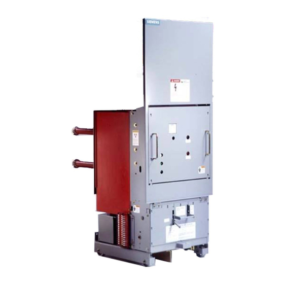
Siemens 15-FSV-750 Instalación Funcionamiento y mantenimiento - Página 8
Navegue en línea o descargue pdf Instalación Funcionamiento y mantenimiento para Interruptor Siemens 15-FSV-750. Siemens 15-FSV-750 48 páginas. Vacuum circuit breakers fsv series and msv series

General
Storage
The c i rcuit breaker should be instal led as soon as possible. I f
storage i s necessary, 'As Found' tests a r e recommended prior
to and after storage for comparison. For storage, the circuit
breakers should be kept indoors in a clean dry protected
location where they will not be exposed to such items as d i rt ,
construction d u s t , corrosive atmosph eres, mechanical ab use
or rapid temperature variation.
Outdoor storage of circuit breakers is not recommended.
If breakers must be stored outdoors, they must be completely
covered and p rotected from the elements. A heat source must
be provided to p revent condensation and subsequent corro
sion. Covering should allow for ventilation. Often 500 watts heat
per breaker is used .
It is recommended that periodic inspection of the breakers be
made during storage and if necessary procedures adjusted to
keep the breakers in proper condition.
"As Found" Tests
When the equipment is received , perform and record "As Found"
insulation tests using megger or Doble tests to give an initial
value for future comparative indication of Insulation change.
Contact resistance tests can also be made using a d u ctor. This
is recommended for al l new c i rcuit breakers especially if they
are to be stored for extended periods , as they may absorb
moisture and contaminants . This s hould also be done after
storage and prior to placing b reakers i nto service.
Changes in values between subsequent tests should be eval
uated and corrective action taken where needed .
Since wide variations can occ u r in insulation values and con
tact resistance because of atmospheric conditions, contami
nation and type of test equi pment, discrete values cannot be
given. However, making and recordi n g these tests on new
equipment, and again at regular intervals, will give a compar
ative indication of insulation and/or contact resistance change.
Maintaining a permanent record of these values for each c i r
cuit breaker should be part of the Maintenance Program.
a. Insulation resistance tests should be made to verify
the insulation integrity. These can include megger
or Dobel tests. If possible, a h i gh-potential test
should be made for one minute at:
RATED
VOLTS
(MAX.)
4.75 kV
8 .2 5 kV
1 5. 0 kV
NOTE:
Before testing the procedu res and safety precautions i n d i
cated in High Potential Testing and I nterrupter Vacuum Check
on page 25 must be reviewed .
Installation Checkout
The following agenda provides a convenient chec k l i st of ac
tivities to be performed while preparing the c i rcuit breaker for
use, and prior to i nsertion into the c u bicle.
Prepare circuit b reaker for insertion i nto its cubicle as follows:
1 .
2 .
TEST VOLTAG E
3 .
A
C .
D . C .
4 .
1 4 ,000
20,000
27,000
38,000
27 , 000
38 ,000
With the b reaker open, check each phase across the
open contacts by connectin g from the u pper to the lower
primary d isconnects. With the circuit breaker closed.
check phase-to-phase and each phase-to-ground
b . A dielectric test on secondary and control circuits should
be made at 1 12 5 volts AC for one minute.
c . I f desi red , contact resistance tests can be made using
a Ductor
d. Make a permanent record of all tests performed .
A
DANGER
Hazardous voltages and h i gh s peed me
chanical parts will cause death or severe
personal i njury and property damage.
Read i nstruction manual , observe safety i n
structions and use to q ualified personnel.
Carefully remove packaging. Note: Vacuum breakers are
normally suppl ied with their primary contacts open . Press
"TRI P" (Red), "close" (black) and again "TR I P" (Red) push
buttons to confirm this i s true. See Fig. 2a & 2b Front
elevations.
Carefully note and c heck rating plate t o ensure maximum
voltage, continuous current, i nterruption rating, and con
trol voltages are compatible with the system and the cu
bicle into which the breaker is to be inserted .
Remove b reaker from the s h i p p i n g s k i d fol lowing require
ments shown pictorially in Figure 1 .
Remove i nterphase and external barriers. Note the i nter
phase barriers are d issimilar from the external barriers.
and that this dissimilarity m u st be recognized when in
stalling the barriers.
Page 3
