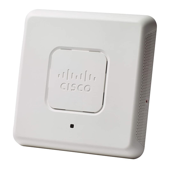
Cisco WAP571 Manual de inicio rápido - Página 5
Navegue en línea o descargue pdf Manual de inicio rápido para Punto de acceso inalámbrico Cisco WAP571. Cisco WAP571 15 páginas. Manually connect access points to the network via power over ethernet (poe)
También para Cisco WAP571: Manual (4 páginas), Manual de inicio rápido (6 páginas)

Insecure mounting might damage the device or cause injury.
W
ARNING
Cisco is not responsible for damages incurred by insecure wall
or ceiling mounting.
To mount the Cisco WAP 571 device to a wall or ceiling:
Determine where you want to mount the device. Verify that the
S
1
TEP
surface is smooth, flat, dry, and sturdy.
Drill two pilot holes into the surface 2.75 inches (70 mm) apart for
S
2
TEP
your Cisco WAP device.
Insert a screw into each hole, leaving a gap between the surface
S
3
TEP
and the base of the screw head.
Place the upper slots of the bracket over the screws, adjust the
S
4
TEP
screws accordingly, and slide the bracket down until the screws fit
snugly into the slots.
Using the bracket as a template, drill two more holes for the lower
S
5
TEP
screws.
Insert a screw into each lower hole.
S
6
TEP
Slide the WAP device into the bracket, placing the cable through
S
7
TEP
the break-out tab found in the back of the bracket.
Connecting the Cisco WAP571 Wireless-
4
AC/N Premium Dual Radio Access Point
with PoE Setup
The WiFi default SSID is "Cisco SB-Setup" with the passphrase "cisco123"
in WPA2-PSK AES. This wireless default configuration will not allow traffic
between WiFi and Ethernet; users will need to go through the setup wizard
to resume the traffic between WiFi and Ethernet.
The user can also perform the initial configuration using a wired Ethernet
connection.
To connect the device to the wired network:
Connect the Ethernet cable to the Ethernet port of a PoE switch.
S
1
TEP
Connect the other end of the network Ethernet cable to the
S
2
TEP
Ethernet port (PoE) of the wireless access point.
Cisco WAP571 Wireless Access Point
4
