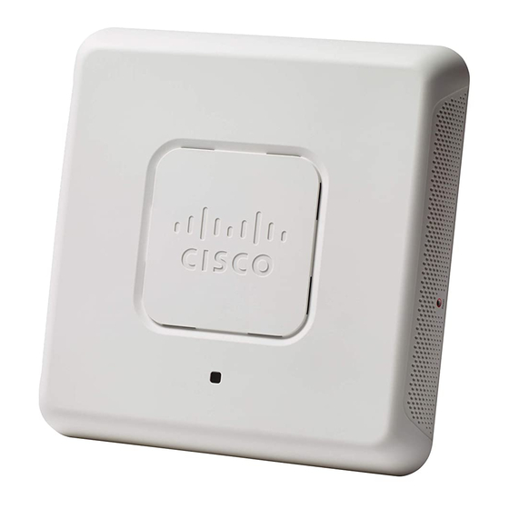
Cisco WAP571 빠른 시작 매뉴얼 - 페이지 5
{카테고리_이름} Cisco WAP571에 대한 빠른 시작 매뉴얼을 온라인으로 검색하거나 PDF를 다운로드하세요. Cisco WAP571 15 페이지. Manually connect access points to the network via power over ethernet (poe)
Cisco WAP571에 대해서도 마찬가지입니다: 매뉴얼 (4 페이지), 빠른 시작 매뉴얼 (6 페이지)

Insecure mounting might damage the device or cause injury.
W
ARNING
Cisco is not responsible for damages incurred by insecure wall
or ceiling mounting.
To mount the Cisco WAP 571 device to a wall or ceiling:
Determine where you want to mount the device. Verify that the
S
1
TEP
surface is smooth, flat, dry, and sturdy.
Drill two pilot holes into the surface 2.75 inches (70 mm) apart for
S
2
TEP
your Cisco WAP device.
Insert a screw into each hole, leaving a gap between the surface
S
3
TEP
and the base of the screw head.
Place the upper slots of the bracket over the screws, adjust the
S
4
TEP
screws accordingly, and slide the bracket down until the screws fit
snugly into the slots.
Using the bracket as a template, drill two more holes for the lower
S
5
TEP
screws.
Insert a screw into each lower hole.
S
6
TEP
Slide the WAP device into the bracket, placing the cable through
S
7
TEP
the break-out tab found in the back of the bracket.
Connecting the Cisco WAP571 Wireless-
4
AC/N Premium Dual Radio Access Point
with PoE Setup
The WiFi default SSID is "Cisco SB-Setup" with the passphrase "cisco123"
in WPA2-PSK AES. This wireless default configuration will not allow traffic
between WiFi and Ethernet; users will need to go through the setup wizard
to resume the traffic between WiFi and Ethernet.
The user can also perform the initial configuration using a wired Ethernet
connection.
To connect the device to the wired network:
Connect the Ethernet cable to the Ethernet port of a PoE switch.
S
1
TEP
Connect the other end of the network Ethernet cable to the
S
2
TEP
Ethernet port (PoE) of the wireless access point.
Cisco WAP571 Wireless Access Point
4
