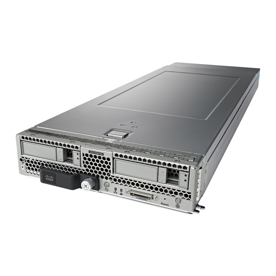
Cisco UCS B200 M4 Nota de instalación y mantenimiento - Página 7
Navegue en línea o descargue pdf Nota de instalación y mantenimiento para Servidor Cisco UCS B200 M4. Cisco UCS B200 M4 30 páginas. For e5-2600 v4 series cpus
También para Cisco UCS B200 M4: Nota de instalación y mantenimiento (46 páginas), Manual de actualización (9 páginas), Manual de mantenimiento (24 páginas)

Installing the Storage Module
Procedure
Step 1
Place the storage module over the two standoff posts on the motherboard at the front of the server.
Step 2
Press down on the drive bay cage where it is labeled "Press Here to Install" until the storage module clicks into place.
Figure 5: Storage Module
Step 3
Using a Phillips-head screwdriver, tighten the four screws to secure the storage module. The locations of the screws are
labeled "Secure Here."
Hard Drive Replacement
The RAID storage module has two front-accessible drive bays that support hot-swappable, 2.5 inch drives. If you purchased the UCS
B200 M4 blade server without the storage module configured as a part of the system, a pair of blanking panels (UCSB-LSTOR-BK)
may be in place. These panels should be removed before installing a hard drive, but should remain in place to ensure proper cooling
and ventilation if the drive bay is unused .
You can remove and install blade server hard drives without removing the blade server from the chassis.
The drives supported in this blade server come with the drive sled attached. Spare drive sleds are not available. A list of currently
supported drives is in the specification sheets at:
http://www.cisco.com/en/US/products/ps10280/products_data_sheets_list.html
7
