Acuity Controls ECLYPSE A1000 Manual de instalación - Página 10
Navegue en línea o descargue pdf Manual de instalación para Controlador Acuity Controls ECLYPSE A1000. Acuity Controls ECLYPSE A1000 10 páginas. Asset tracking
También para Acuity Controls ECLYPSE A1000: Manual de instalación (14 páginas)

7.0 - Sub-gigahertz Assets Adapter
Mounting Instructions
Figure 14: Ceiling Mounting
7.3 Instructions for NPT Mounting
1. Remove the 3/4 inch electrical panel knockout or use
a 01.115" (26.9 to 32.5mm) hole punch to create a
mounting hole position.
2. Unbox the Assets Adapter, remove nut from the
adapter, make sure the gasket is on the adapter,
place nut on the USB cable and hand tighten nut to
the enclosure.
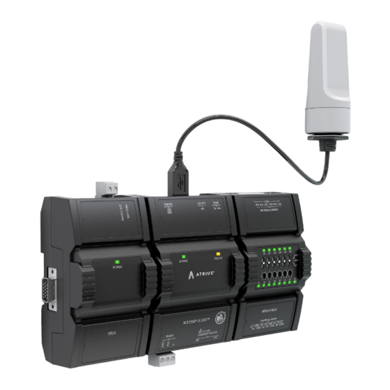
3. Plug-in the USB connector into the USB host slot on
the ECLYPSE.
Do not mount a wireless adapter inside of metal enclosures.
Figure 15: Wireless Adapter Installation
7.4 Location Tips for ECLYPSE A1000AT using
Wireless Adapters
When installing a wireless adapter, it is important to
ensure that distances and obstructions do not impede
Acuity Brands | One Lithonia Way Conyers, GA 30012 Phone: 800.535.2465 www.acuitycontrols.com © 2017-2019 Acuity Brands Lighting, Inc. All rights reserved. 03/29/19
NUT
INTERNAL TOOTH
LOCK WASHER
GASKET
SUSPENDED CEILING
PANEL/MOUNTING
SUPPORT
ADAPTER
transmission. Metallic parts, such as reinforcement in
walls, machinery, office furniture, etc. are major sources
of field strength dampening. Furthermore, supply areas
and elevators shafts should be considered as complete
transmission screens. See Figure 16.
Figure 16: Wireless Transmission Screens
For transmission obstructions, one way to get around
an obstruction, such as a duct, is to place the wireless
adapter on the side of the obstruction that is nearer to
the coordinating wireless device, even if the controller is
on the opposite side of the obstruction. But always keep
in mind that the wireless adapter performs best when it
is away from metal objects or surfaces.
Two common sources of the wireless obstructions in the
field are when the wireless adapter is placed in a high
angle of incidence and when two wireless adapters are
placed along the same wall. A steep angle of incidence
may cause a signal to run through more obstructions
than realized, dampening the signal. Therefore it is
preferable that the transmission be arranged so that it
travels straight or perpendicuarly through the obstruc-
tion. See Figure 17.
Linked wireless adapters should not be mounted on the
same wall or plane. Radio waves are subject to interfer-
ing reflections. It is always best to place the linked wire-
less antennas on the side or opposite walls. See Figure
18 .
Figure 17: High Angle of Incidence
Figure 18: Wall Reflectance
A1000AT_IG_10_EN
10 of 10
