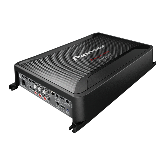
Pioneer GM-D9605 Manual de servicio - Página 4
Navegue en línea o descargue pdf Manual de servicio para Amplificador Pioneer GM-D9605. Pioneer GM-D9605 29 páginas. Bridgeable four-channel power amplifier

1
1.3 NOTES ON REPLACING PARTS
Be careful in handling ICs. Some ICs such as MOS type are so fragile that they can be damaged by electrostatic
induction.
A
Please attach the Sheet between Power Transistor and Heat Sink when you place Power Transistor in Heat Sink.
If the Sheet is not attached between Power Transistor and Heat Sink, Power Transistor might be damaged.
When you replace sheets (#9 (16170201000) & #10 (16170201000) on the page 14), re-apply silicon
grease (GEM1057) after wiping off silicon grease.
The part listed below is difficult to replace as a discrete component part.
When the part listed in the table is defective, replace whole Assy.
Unit Name
Amp Unit
Amp Unit
Amp Unit
Amp Unit
B
Amp Unit
When you replace a part fixed to the heatsink (Q515~518, Q716~718, Q720~722, D720~723, Q731, 732, IC703 and
704), adjust the position of the part according to the following procedure.
C
D
E
F
4
1
2
Ref No.
IC113
IRS2093
Q105/106
IRF6775M
Q205/206
IRF6775M
Q305/306
IRF6775M
Q405/406
IRF6775M
GM-D9605/XEEL
2
3
Part No.
Remarks
There back heat pad
Special MOSFET
Special MOSFET
Special MOSFET
Special MOSFET
Put the Amp Unit on blocks.
Put a paper between the block and the Amp Unit,
and outline transistors and diodes.
Put a part to replace in the outline.
3
4
4
