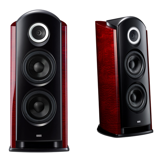
Pioneer TAD-R1 Manual de servicio - Página 9
Navegue en línea o descargue pdf Manual de servicio para Sistema de altavoces Pioneer TAD-R1. Pioneer TAD-R1 17 páginas.

5
3.4 CABINET
Inside the cabinet
Left: Red (TW)
Right: Green (MID)
Bundle the two cables, pass them
through the front side of the crosspiece,
then tie them with the banding band.
10
22 (x5)
Black (WF)
Bundle the two cables, pass them through at
the left of the crosspiece, then fix them with
the banding band.
Run the cable for the upper woofer beneath
the crosspiece and pull it up through the
center hole.
Black (WF)
CRT ASSY
12
1. Adhere the packing to the rear of the
CST trim ring. Be careful that the packing
does not protrude outside of the inner
circumference.
• SPEAKER SYSTEM Parts List
Mark No.
Description
NSP 1
Cabinet Assy
2
Network Assy (LPF)
NSP 3
Terminal Assy
4
Connecting Cord (TW)
5
Connecting Cord (MID)
6
TAD Badge
NSP 7
Country Label
8
Packing (CST)
9
Packing (WF)
10
Cusion (WF)
11
Gasket (CST)
12
Packing
(CST Mesh,Connecting Cord)
5
6
5
4
13
13
10
15
17
Direction of the mesh pattern lines
(Front)
(Rear)
2. Push the mesh screen so that the concave side faces the
front. Align the marker line on the trim ring with the cutout
of the mesh screen.
If they are properly aligned, the mesh pattern lines of the
mesh screen form an angle of 45° with the marker line.
Part No.
SMM2043
SWN1785
SWT1057
SDD1351
SDD1352
SAM1512
SAN3782
SEC2101
SEC2102
SEC2103
SEC2107
SEC2109
6
7
Wind the packing around the cables,
as shown in the figure in the box below.
Pass the cables through the holes on
the partition board from below, and pull
the cables up until the packing material
comes to the holes. Pour the hot-melt
adhesive into the holes to secure the
cables.
Left: LPF OUTPUT
2
Secure it at the inside of
the rear panel with the
tapping screw.
Right: LPF INPUT
Bundle the two cables, pass
them through the front side
of the crosspiece, then tie
them with the banding band.
13
Bundle the two cables, pass
them through behind the
crosspiece, then tie them
with the banding band
Upper: Red (HPF)
Middle: Black (WF IN)
Lower: Green (MPF)
4, 5
21 (x4)
Marker line
Cutout of the
mesh screen
Marker hole
3. Place the CST unit so that the MID terminal
faces the marker hole on the trim ring then
secure the unit with the screws.
Mark No.
Description
NSP 13
Wire Tie 300mm
14
Trim Ring (WF)
15
Trim Ring (CST)
16
Grill Assy
17
Mesh (CST)
18
Screw Cap
19
Speaker 25
20
Speaker 16
21
Screw
22
Screw (WF Network)
23
Hexagon Socket Screw
(Terminal Assy)
24
Screw
25
Screw
TAD-R1
7
8
Screw (SBA1278)
Laurette
Wind the packing several times
until its thickness becomes the
designated size. After adjusting
12
for the thickness of the packing,
cut off the unnecessary remaining
packing material.
Marker hole
20
MID terminal
Part No.
SEP6024
SLA1059
SLA1060
SMG1882
SNC1212
SNK2943
SWC1016
SWX1034
BMZ40P100S
BYC35P200FTB
SBA1278
SMZ40H120S
SMZ50H550S
8
A
B
C
D
E
F
9
