Alemite 9949 Manual de servicio - Página 9
Navegue en línea o descargue pdf Manual de servicio para Bomba de agua Alemite 9949. Alemite 9949 14 páginas. High-pressure pump stripped and portable
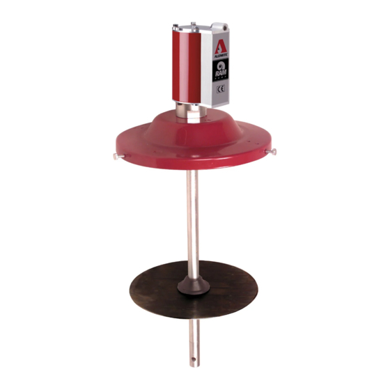
High-Pressure Pump (Stripped and Portable)
• Use a solid round bar or other suitable tool.
NOTE: The pump tube will break at one of
three places. Unscrew the separated portion
from the inner components of the pump tube
assembly.
19. Pull the entire rod assembly from the pump tube.
20. Unscrew the remaining sections of the pump tube.
• Use a strap wrench.
Pump Tube (Inner Components)
21. Remove Gasket (46), Seat (54), additional Gasket
(46), Foot Valve (53) [with Seal (52)], and Stop (51)
from the bottom of Lower Tube (50).
• Remove the Seal from the Foot Valve.
22. Remove Bearing (47), Seal (48), and additional
Bearing (47) from the top of the Lower Tube.
23. Remove Gasket (46) from Tube (45).
Rod Assembly
24. Remove Roll Pin (44) that secures Primer Rod to
Piston (43).
• Use a punch and a small hammer.
25. Unscrew the Primer Rod from the Piston.
26. Remove Roll Pin (38) that secures Extension (39) to
the Piston.
• Use a punch and a small hammer.
27. Unscrew the Extension from the Piston.
28. Remove Spring Guide (40), Spring (41), and Ball (42)
from the Piston.
29. Remove Roll Pin (38) that secures Upper Rod (37) to
the Extension as required
• Use a punch and a small hammer.
30. Unscrew the Upper Rod from the Extension.
Body
31. Remove Gasket (31) from the Body.
32. Remove Bearing (36), Seal (35), Lantern Ring (34),
and Seal (33) from the Body.
33. Remove O-Ring (29) from the Body.
Alemite Corporation
Clean and Inspect
NOTE: Use the appropriate repair kit for
replacement parts. Make sure all the compo-
nents are included in the kit before discard-
ing used parts.
1. Clean all metal parts in cleaning solvent. The solvent
should be environmentally safe.
2. Inspect all parts for wear and/or damage.
• Replace as necessary.
3. Inspect Air Piston (26) for fatigue cracks.
• Replace as necessary.
4. Inspect Upper Rod (37), Piston (43), and Primer Rod
(49) closely. Use a magnifying glass to detect any
score marks on the components.
• Replace as necessary.
5. Closely inspect the mating surfaces of Foot Valve (53)
and Seat (54) for any imperfections.
• Ensure a smooth and clean contact is obtained.
6. Install Ball (42) into Piston (43). Fill the Piston with
solvent.
• Make sure no leakage occurs.
7. Inspect the corners of Stop (51) for breakage. Place the
Stop into the bottom of Lower Tube (50).
• Make sure the Stop is secure within the Tube when
pressure is applied.
Assembly
NOTE: Prior to assembly, certain compo-
nents require lubrication. Refer to Table 3
for details.
Item No.
Description
Quad-Ring, 2-5/8 " ID x 3 " OD
26
29
O-Ring, 2-3/4 " ID x 3 " OD
27
O-Ring, 3/8 " ID x 1/2 " OD
33
Seal, 1/2 " ID x 3/4 " OD
35
Seal, 1/2 " ID x 7/8 " OD
48
Seal, 5/8 " ID x 1 " OD
52
Seal, 3/8 " ID x 5/8 " OD
Table 3 Lubricated Components
9
SER 9940
Type of Lubricant
Teflon Grease
Oil
Revision (2-03)