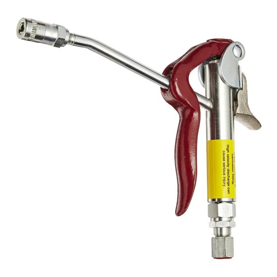
Alemite 6320-3 Manual de servicio - Página 8
Navegue en línea o descargue pdf Manual de servicio para Unidad de control Alemite 6320-3. Alemite 6320-3 10 páginas. High-pressure control valve

SER 6320-3
Installation
Attach the Z-Swivel to the control valve's Inlet
Adapter (18). Tighten connection securely.
Operation and Adjustments
WARNING
Should leakage occur anywhere within the
system, disconnect power to the motor. Personal
injury can occur.
Prime and Test
NOTE: Perform the following procedures at
a pressure not to exceed 3000 psi (207 Bars).
Should valve leakage occur at anytime, refer
to the Troubleshooting Chart.
1. Place the pump in the product to be dispensed.
2. Point the control valve into an appropriate collection
container.
3. Connect the air line to the pump motor.
• The control valve should show no leakage or
dispense the product.
4. Depress the control valve Lever (2) fully.
• Product should flow continuously once air is
eliminated from the control valve (and system).
If the control valve does not dispense the
product, refer to the Troubleshooting
Chart.
5. Release the Lever.
If product appears at Coupler (26):
6. Turn Setscrew (1) counterclockwise until the product
discontinues to flow.
Product Delivery Adjustment (Single-Shot)
IMPORTANT: The adjustment for the single-
s h o t m o d e - o f - o p e r a t i o n e f f e c t s t h e
continuous mode-of-operation. If the single-
s h o t a d j u s t m e n t i s s e t t o o g re a t , t h e
continuous mode-of-operation may be lost.
1. Depress the control valve Lever (2) partially to initiate
the single-shot mode of operation.
Revision (1-13)
If product does not begin to flow or too great
(or too little) an amount is produced, adjustment is
necessary.
2. Make sure to read the following warning.
WARNING
Release all pressure within the system
prior to valve adjustment.
•
Disconnect the air supply line from the pump
motor.
•
Into an appropriate container, operate the
control valve to discharge remaining pressure
within the system.
Personal injury can occur.
3. Loosen Locknut (20) 1/8 turn. See Figure 5.
• Do not allow the Locknut to completely disengage
Single-Shot Adjuster (24).
23
22
24
21
20
19
18
Refer to Figure 2 Parts List
for Parts Identification
Figure 5 Single-Shot Adjustment Components
WARNING
Do not turn the Single-Shot Adjuster
counterclockwise more than a total of four turns.
Personal injury can occur.
8
High-Pressure Control Valve
17
Alemite LLC
