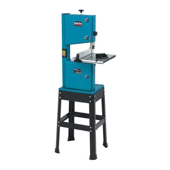
Clarke WOODWORKER CBS250 Instrucciones de uso y mantenimiento - Página 8
Navegue en línea o descargue pdf Instrucciones de uso y mantenimiento para Sierra Clarke WOODWORKER CBS250. Clarke WOODWORKER CBS250 20 páginas. 45 mm (10”) bandsaw & stand
También para Clarke WOODWORKER CBS250: Manual de instrucciones de funcionamiento y mantenimiento (13 páginas)

ASSEMBLY
Stand
(Refer to Fig.2)
1.
Assemble sub assy x 2, see fig. 3.
Parts required per assy, 2 legs (L), 1 short beam (H), 1 short
cross member (D), and 8 short round head screws nuts and
washers.
Do not tighten nuts at this stage.
NOTE: Beams and cross members fit inside the legs. Screws are fitted
from the outside with washers and nuts on the inside.
2.
Connect sub assy's together using 2 long cross members (E),
2 long beam's (G), and 8 short round head screws with nuts
and washers, 8 short hex head bolts with washers and nuts,
Do not tighten nuts at this stage.
NOTE: Long beams are fitted on top of short beam's see Fig .4. Hex head
bolts are fitted from the top with washers and nuts on the underside.
3.
Invert the stand and push on the rubber feet.
4.
Turn stand over onto it's feet again and only when
satisfied that it is completely stable, fully tighten all nuts.
Mounting the machine
5.
With assistance, carefully lift the machine on to the stand.
6.
Line up the corner holes and secure the machine to
the stand using, 4 long hex head bolts, from the top,
with washers and nuts on the underside. Fit all four
bolts before finally tightening all nuts, progressively,
taking care not to overtighten.
7.
Manouvre the table (M) carefully so that the the
blade passes through the slot in the table, and
mount the table on to the trunnion - see Fig.5,
8.
Insert the table securing screws and position the
table so that the saw blade runs in the centre of
the table insert. When satisfied, tighten the screws
securely.
Setting The Table Square With The Sawblade
9.
Set the table square to the sawblade by slackening the
lock knob, shown in Fig.6, then adjusting the table so that
the pointer lines up with the '0' position on the scale.
NOTE: The table can be tilted up to 45° to the sawblade.
To tilt the table, slacken the lock knob (Fig.6), tilt the table
to the desired angle as indicated on the scale then retighten
the lock knob. It is recommended to check the correct
angle setting, by making trial cuts in scrap pieces of wood.
Trunnion
8
Fig.3
Fig.4
A
Fig.5
B
Fig.6
