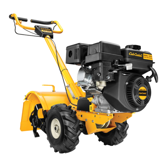
Cub Cadet RT 35 Rear-Tine Garden Tiller Manual del usuario - Página 11
Navegue en línea o descargue pdf Manual del usuario para Cultivador Cub Cadet RT 35 Rear-Tine Garden Tiller. Cub Cadet RT 35 Rear-Tine Garden Tiller 16 páginas. Rear tine tiller
También para Cub Cadet RT 35 Rear-Tine Garden Tiller: Folleto y especificaciones (2 páginas), Garantía limitada (1 páginas)

3.
Remove the four 1⁄ 4 -20 hex washer screws that
secure the pulley shield to the frame as seen in
Figure 5-4, and remove the pulley shield and
set aside in a safe location until reinstallation.
Figure 5-4
4.
Remove the idler bracket extension spring
from the idler bracket using a pair of needle-
nosed pliers. Grab the spring by the end
that hooks over the frame, pull it away from
the frame, then up and carefully relieve the
tension of the spring. See Figure 5-5.
Drive Cable
Remove
the idler
bracket
extension
spring
Figure 5-5
5.
Unhook the drive cable from the idler bracket.
See Figure 5-5.
6.
Remove the belt from the transmission, engine
and idler pulleys.
7.
Replace the old belt with a new belt. Make
sure the belt is installed into the pulleys
closest to the tines/front of the tiller.
8.
Re-install the drive cable on the idler pulley.
9.
Carefully re-install the idler bracket extension
spring on the idler bracket.
10.
Reassemble the tiller in the reverse order in
which it was disassembled.
NOTE: When reinstalling the belt cover, be sure
to engage the bail and hold it so that the drive
belt is tight before attempting to reinstall the
belt cover. This will enable the belt to fall under
the belt keeping mechanism built into the belt
cover. Failure to do so could damage the belt
and/or belt cover.
Tines
The tines will wear with use and should be inspected
at the beginning of each tilling season and after
every 30 operating hours. The tines can be replaced.
Refer to the Illustrated Parts List manual for part
numbers and ordering instructions.
Tine Inspection
With use, the tines will become shorter, narrower and
pointed. Badly worn tines will result in a loss of tilling
depth, and reduced effectiveness when chopping up
and turning under organic matter.
Removing/Installing a Tine Assembly
1.
Remove the tine shield end covers and side
shields by removing the three wing nuts on
each side that secure them.
Hex
2.
A tine assembly consists of a left hand tine
Washer
assembly and a right hand tine assembly.
Screws
NOTE: The tine assembly moves in a counter-
rotating motion with the sharp edges of
the tines positioned to enter the soil first
when counter-rotating. Note this position
of the tines for reinstallation of the new tine
assemblies.
3.
To remove a tine assembly, simply remove the
cotter pin securing the clevis pin as seen in
Figure 5-6. Remove the clevis pin and slide the
assembly to the outside of the unit and off of
the tine shaft.
Cotter Pin
Figure 5-6
4.
Before reinstalling the tine assembly, inspect
the tine shaft for rust, rough spots or burrs.
Lightly file or sand, as needed. Apply a thin
coat of grease to the shaft.
5.
Install each tine assembly so that the cutting
(sharp) edge of the tines will enter the soil first
when the tiller moves forward. Keep in mind
that these tines are counter rotating, so secure
the tine assembly to the tine shaft using the
clevis pin and internal cotter pin.
Change Transmission Gear Oil
NOTE: The transmission gear oil does not need to be
changed unless it has been contaminated with dirt,
sand or metal particles.
See an authorized service dealer to have the
transmission gear oil changed. Refer to the phone
numbers on page 2 of this manual to locate the
nearest service dealer.
Clevis Pin
S
5 — S
11
ection
ervice
