AIMS PWRINV800W Manual del usuario - Página 2
Navegue en línea o descargue pdf Manual del usuario para Inversor AIMS PWRINV800W. AIMS PWRINV800W 6 páginas. 800 watt power inverter

Welcome
This product has been carefully engineered and manufactured to
give you dependable operation. Please read this manual thoroghly before
operating your new product, as it contains information, you need to become
familiar with. The manual details the inverter's features and allows you to
obain the performance that will bring you continued enjoyment for many years.
Please keep this manual on file for future reference.
How Power Inverters Work
Power inverters convert low voltage DC (direct current) power to 110/120-volt
AC (alternating current) household power. This conversion process thereby
allows you to use household products, power tools, and other electronic
products away from normal AC power sources (standard 110/120V wall outlets).
Depending on the model and its rated capacity, inverters can draw power either
from standard 12-volt automobile and marine batteries or from portable high
power 12-volt power sources.
The waveform that is generated by this conversion is a "modified sine wave" .
The modified sine wave produced by our inverters has a root square mean
(RMS) voltage of 110/120 volts, which is the same as standard household power.
The majority of AC voltmeters are calibrated for RMS voltage under the
assumption that the measured waveform will be a pure sine wave. Therefore,
these meters will not read the RMS modified sine wave voltage correctly.
They will read about 20 to 30 volts too low. To accurately measure the output
voltage of the inverter, use a true RMS reading voltmeter such as a Fluke 87,
Fluke 8060A, Beckman 4410, Triplett 4200 or any voltmeter identified as a "true
RMS" .
Controls and Components
Front Panel
1. ON/OFF Power Switch
2. Green LED Indicator Light
3. Red LED Indicator Light
4. 110/120 Volt AC Outlets
5. Protective Outlet Covers
4
Power Inverter 800W
5
3
2
1
1
Rear Panel
6. Power Input Terminal
Black = Negative
7. Cooling Fan
8. Power Input Terminal
Red = Positive
9. Battery Cables and Clips
Connect these terminals to the color
coded terminals on the back panel
of the inverter
9
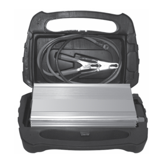
Storage Case (For 800W
Models ONLY)
Owner's Manual
8
7
6
Connect these color coded cable
clamps to your battery terminals
(Red-positive, Black-negative)
2
