Altronic CDM-2100 Manual de instrucciones - Página 3
Navegue en línea o descargue pdf Manual de instrucciones para Instrumentos de medida Altronic CDM-2100. Altronic CDM-2100 20 páginas. Differential pressure monitor

1.0 OVERVIEW
1.1
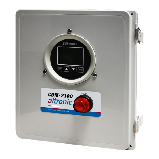
The CDM-2100 control panel consists of the DSG-1611DUPS instrument, wiring
terminals, and fuse installed in an industrial enclosure.
1.2 The CDM-2100 controller is a dedicated electronic microprocessor-based system
designed to sense differential pressure across a single catalyst element. A front
mounted keypad serves as the user interface for all required system configuration.
A backlit 128 x 64 character graphic display shows system status, programmed
controller parameters and channel labels. The controller provides complete
supervisory and alarm annunciation capability dedicated to monitoring and
protecting catalyst elements indicating when internal pressures have risen above
manufacturers limits.
In conjunction with the CDM-2100 controller, a highly accurate, low pressure
inches of water column differential pressure transmitter is used. When each port
of the differential pressure transmitter is placed across the catalyst element,
it sends an electronic signal back to the CDM-2100. This signal represents the
amount of pressure drop across the catalyst element.
2.0 CDM-2100 PANEL
2.1
The panel contains all the necessary hardware and provides the wiring interface
to an external sensor. Conduit openings at the bottom of the enclosure provide
access for supply power, sensor and other necessary wiring.
3.0 CDM-2100 DISPLAY MODULE
3.1
The CDM-2100 display module provides for monitoring the catalyst differential
pressure. The output of the CDM-2100 instrument provides a 4-20mA signal
representing the incoming pressure, and alarm outputs as discrete contacts.
3.2 The keypad is a sealed membrane unit containing MENU/ESC, UP, DOWN and
ENTER keys, used to navigate through channel status and description and to
edit the setpoints.
3.3 The LCD has a Home Screen that displays a Status Line, along with the catalyst
differential pressure in inH2O.
3.4 The keypad and display are used to navigate through channel status and
descriptions, view screens, and to view or edit the system's configuration.
Pressing the MENU/ESC key advances the display to the menus. All menu
adjustments are saved in non-volatile EEPROM memory by pressing the ENTER
key. The EEPROM memory retains the current configuration during normal
operation, after engine shutdown and a system power-down.
3.5 The CDM-2100 has serial communications compliant to Modbus RTU standard
and uses RS-485 for its hardware communication format.
4.0 MOUNTING THE PANEL
4.1
Mount the control panel(s) to a post or to a suitable flat surface so that the
display is at a convenient viewing height.
CDM-2100 OM 3-21
All rights reserved © ALTRONIC, LLC 2021
(FIG. 1)
3
NOTE: Avoid mounting the panel
with the LCD display facing direct
sunlight. The display operating
temperature range is -31°F to +176°F
(-35°C to +80°C). The panel(s)
should be mounted within 10–20
feet of the engine, the fuel solenoid
valve and sensors.
