CVS Controls CVS1000L Manual del producto - Página 5
Navegue en línea o descargue pdf Manual del producto para Posicionadores de válvulas CVS Controls CVS1000L. CVS Controls CVS1000L 13 páginas. 1000l electro-pneumatic linear positioner
INSTALLATION
Safety Warning
When installing the positioner, please ensure you read
and follow the safety instructions.
•
All input and supply pressure to valve, actuator,
and other related devices must be turned off.
Use the bypass valve or other equipment to avoid
•
an entire system "shut down".
Make sure there is no remaining pressure in the
•
actuator.
YT-1000L Installation
YT-1000L should be installed on a linear motion valve
such as a globe or gate valve using a spring return
type diaphragm or piston actuator. Before installation,
be sure to check for the following installation
components.
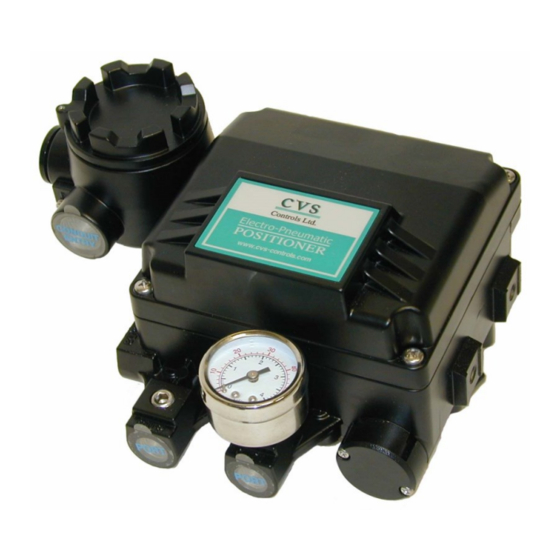
1. YT-1000L main body
2. Feedback lever and lever spring
3. Flange nut (bottom side of YT-1000L)
4. 4 pcs. of hexagon head bolts (M8 X 1.25P)
5. 4 pcs. of M8 plate washer
Installation Steps:
1. A proper bracket must be made in order to attach
the positioner on the actuator yoke. Please consider
the following when making a bracket.
i) Feedback level should be leveled at 50% of the
valve stroke. (Refer to step 7.)
ii) Feedback lever connection bar of actuator clamp
should be installed at the position that the valve stroke
and number, indicated on the feedback, should be
fitted. (Refer to step 8.)
2. Attach YT-1000L to the bracket, which was
produced in the earlier step, by using bolts. (Figure 2)
Please refer to the backside of the product for size of
bolts. The standard size of bolt is M8 X 1.25P.
Product Manual: CVS Rack & Pinion Actuator
3. Attach YT-1000L (with bracket) to the actuator yoke.
DO NOT TIGHTEN COMPLETLEY.
4. Connect YT-1000L feedback lever to the actuator
clamp. The gap on the YT-1000L feedback lever is
6.5mm. The connection bar thickness should be less
than 6.3mm. (Figure 3)
5. Connect the air filter regulator to the actuator tem-
porarily. Set supply pressure of the regulator in order
to position the actuator clamp at 50% of the valve
stroke.
(Figure 4 next page)
50
5
CVS Controls Ltd.
6.5mm
CVS Controls Ltd.
Process Management
And Instrumentation