DOLD IP 5883 Instalación / Técnica de control - Página 2
Navegue en línea o descargue pdf Instalación / Técnica de control para Instrumentos de medida DOLD IP 5883. DOLD IP 5883 6 páginas. Varimeter rcm

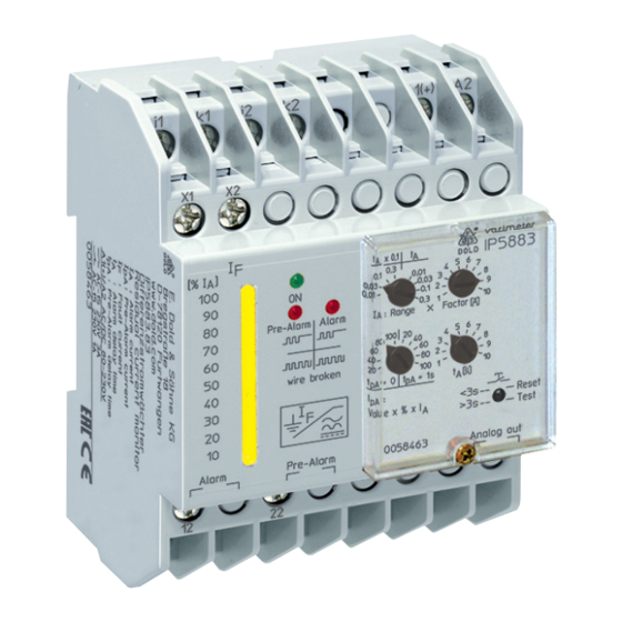
Set-up and Adjustment Facilities
LED "ON"
Aux.voltage
connected
LED "pre-alarm"
LED "Alarm"
LED chain
M9237_g
It is of advantage to keep the range small and the Factor high.
Example: Setting 300 mA: Range 0,1 x Factor 3 = 300 mA
Function
The Measuring circuit includes an external residual current transformer.
All conductors of a voltage system are fed through the transformer except
the ground wire. In a healthy system the sum of all flowing currents is zero,
so that no voltage is induced in the CT. If an earth fault occurs, sourcing
a current flowing to ground, the current difference induces a current in
the CT that is detected by the IP 5883. If an earth fault occurs, sourcing a
current flowing to ground, the current difference induces a current in the
CT that is detected by the IP 5883.
On broken sensor wires and broken CT coils the unit goes into alarm state
and the both red LEDs for pre-alarm and alarm flashes.
The unit has 2 changeover output contacts. One for alarm 11, 12, 14 and
21, 22, 24 and one for pre-alarm.
4 Setting Ranges can be slected from 10 mA to 3 A. The fine adjustment
is made via potentiometer „Factor"
Measuring range = Range x Factor.
The alarm relay switches at 100 % of the adjusted response value.
The pre-alarm can be set between 20, 40, 60, 80 and 100 % of the alarm
value.
Via rotary switch „t
" the time delay of the alarm relay can be adjusted in
A
2 ranges. Within the chosen range the value is adjusted on rotary switch
„Range".
t
x 0,1: t
= 0.1 ... 1s ;
A
A
For the time delay of the pre-alarm 2 settings are available.
t
= 0 and t
= 1s
pa
pa
The different CT sizes require a correct adaption of the residual current
monitor. 3 models are available:
Type
Frequeny range
IP 5883
DC + AC up to 250 Hz
IP 5883/070
DC + AC up to 180 Hz
IP 5883/140
DC + AC up to 60 Hz
Table 1
t
x 1: t
= 1 ... 10s
A
A
Suitable
residual current
transformer
ND 5018/030
ND 5018/035
ND 5018/070
ND 5018/105
ND 5018/140
ND 5018/210
t A : switching delay alarm
t A x 0,1
t A x 1
I A : I alarm
I A = Range x Factor [A]
t A : switching delay alarm (s)
t A =
t A x 0,1 t A x 1
t pA : switching delay pre-alarm
tpA = 0
tpA = 1s
I pA : prealarm
I pA = tripping value x setting in %
Pushbutton
<3s = reset fault memory
>3s = devise test
An external link on X1-X2 allows the change between energized and de-
energized on trip. A change of the function will only be valid after interrup-
tion of the supply voltage.
Terminal X1 / X2:
External link
Open
De-energized on trip: In the case of groundfault or missing auxiliary supply
the relays are de-energized,
the NC contacts 11/12; 21/22 are closed
In fault free state the relays are energized,
the NO contacts 11/14; 21/24 are closed
Energized on trip:
In the case of groundfault the relays are energized,
the NO contacts 11/14; 21/24 are closed
In fault free state the relays are de-energized,
the NC contacts 11/12; 21/22 are closed
If an adjusted value is reached on the measuring input (alarm or pre-
warning)at the standard type IP 5883 the signal is stored. Reset is made
by pressing the button „Test/Reset" for < 3 s s or by disconnecting the
auxiliary supply (approx. 30 s).
If the „Test/Reset" button is pressed for > 3 s, a test of the unit is made.
The time delays run, the pre-warning and alarm is activated.
An LED chain shows the fault current between 10 and 100 % of the adju-
sted alarm value.
An analogue output 0 ... 10 V indicates also the fault current. 10 V corre-
sponds to 100 % of the adjusted alarm value.
2
=
De-energized on trip,
=
Energized on trip
11.01.21 en / 335A
