DOLD IP 5883 Instalación / Técnica de control - Página 3
Navegue en línea o descargue pdf Instalación / Técnica de control para Instrumentos de medida DOLD IP 5883. DOLD IP 5883 6 páginas. Varimeter rcm

Settings
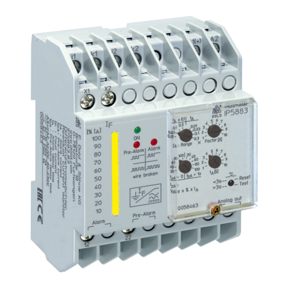
Front detail with potentiometers
M11437
Example 1
Alarm at 1.5 A (0.3 A x 5)
Time delay alarm:
t
= 1 x 7 s
A
Pre-warning at
80 % of alarm value, 1.2 A
Time delay pre-warning:
t
= 0 s
pa
Technical Data
Input
Auxiliary voltage U
:
H
Voltage range:
Nominal frequency U
:
H
Nominal consumption
At AC:
At DC:
Measuring range:
Measuring range
fine adjustment:
Max. overload:
Pre-warning:
Frequency range:
Repeat accuracy:
Temperature drift:
Reaction time:
Switching delay
pre-warning:
Switching delay alarm:
Output
Contacts:
Thermal current I
:
th
Switching capacity
At AC 15:
NO contact:
NC contact:
Electrical life
To AC 15 at 1 A, AC 230 V:
Short circuit strength
max. fuse rating:
Mechanical life:
Example 2
Alarm at 100 mA (0.01 A x 10)
Time delay alarm:
t
= 0.1 x 5 s
A
Pre-warning at
40 % of alarm value, 40 mA
Time delay pre-warning:
t
= 1 s
pa
AC/DC 24 ... 80 V, AC/DC 80 ... 230 V
DC 19 ... 110 V, AC 19 ... 90 V,
DC 64 ... 300 V, AC 64 ... 265 V
AC 50 / 60 Hz
5 VA
2.5 W
10 ... 100 mA, 30 ... 300 mA,
100 ... 1000 mA, 300 ... 3000 mA
1 ... 10
With overload protection
20, 40, 60, 80, 100 %
DC and AC to 250 Hz*
)
*
depending on the differential current
)
transformer used. See „Function" Table 1.
≤ ± 3 %
≤ ± 0.1 % / K
< 50 ms
Without delay or 1 s adjustable
x 0.1, x 1, fine adjustment 1 ... 10
1 changeover contact for pre-warning,
1 changeover contact for alarm
5 A
3 A / AC 230 V
IEC/EN 60947-5-1
1 A / AC 230 V
IEC/EN 60947-5-1
3 x 10
switch. cycl.
IEC/EN 60947-5-1
5
4 A gG /gL
IEC/EN 60947-5-1
≥ 10
switching cycles
8
Technical Data
Analogue Output
Terminal U+ / U-:
If using the analogue output "U+ / U-" you have to use a shielded
cable. The shield has to be grounded one end to PE at the device.
General Data
Operating mode:
Temperature range
Operation:
Storage:
Altitude:
Insulation coordination
according to IEC 60664-1:
RN 5883 cennected with
current transformer ND 5018
Rated voltage:
Rated impuls voltage /
M9467
pollution degree:
Auxiliary voltage / Meas. circuit: 6 kV / 2
Auxiliary voltage / Contacts:
Auxiliary voltage / Analoge output: 6 kV / 2
Contacts / Analoge output:
Meas. circuit / Analoge output:
Contacts 11,12,14 / 21, 22, 24: 4 kV / 2
EMC
Surge voltages:
Electrostatic discharge:
HF-irradiation
80 MHz ... 1 GHz:
1 GHz ... 2.7 GHz:
HF-wire guided:
Fast transients:
Surge voltages:
Interference suppression:
Degree of protection
Housing:
Terminals:
Housing:
Vibration resistance:
Climate resistance:
Terminal designation:
Wire connection
Cross section:
Stripping length:
Wire fixing:
Fixing torque:
Mounting:
Weight:
Dimensions
Width x height x depth:
Classification to DIN EN 50155 for IP 5883
Vibration and
shock resistance:
Ambient temperature:
Protective coating of the PCB: No
Accessories
ET 4086-0-2:
3
0 ... 10 V; 5 mA
Continuous
- 40 ... + 60 °C
- 40 ... + 70 °C
< 2000 m
800 V
4 kV / 2
4 kV / 2
6 kV / 2
Class 3 (5 kV / 0,5 J) DIN VDE 0435-303
8 kV (air)
IEC/EN 61000-4-2
IEC/EN 61000-4-3, DIN EN 50121-3-2
20 V / m
10 V / m
10 V (class 3)
IEC/EN 61000-4-6
2 kV (class 3)
IEC/EN 61000-4-4
2 kV (class 4)
IEC/EN 61000-4-5
Limit value class B
EN 55011
IP 40
IEC/EN 60529
IP 20
IEC/EN 60529
Thermoplastic with V0-behaviour
according UL subject 94
Amplitude 0.35 mm
frequency 10 ... 55 Hz IEC/EN 60068-2-6
40 / 60 / 03
IEC/EN 60068-1
EN 50005
2 x 2.5 mm
2
solid or
2 x 1.5 mm
stranded wire with sleeve
2
DIN 46228-1/-2/-3/-4
10 mm
Flat terminals with self-lifting
clamping piece
0.8 Nm
DIN rail mounting (IEC/EN 60715) or
screw mounting M4, 90 mm hole pattern,
with additional clip available as accessory
220 g
70 x 90 x 63 mm
Category 1, Class B
IEC/EN 61373
T1, T2 compliant
T3 and TX with operational limitations
Additional clip for screw mounting
Article number: 0046578
11.01.21 en / 335A
