Floe VSD 6000 Manuel d'instructions de montage - Page 6
Parcourez en ligne ou téléchargez le pdf Manuel d'instructions de montage pour {nom_de_la_catégorie} Floe VSD 6000. Floe VSD 6000 12 pages. Full length pontoon & tri-toon bunks large lifts
Également pour Floe VSD 6000 : Manuel d'instructions pour l'assemblage (12 pages), Manuel d'instructions de montage (8 pages), Manuel d'instructions de montage (16 pages)

ST EP 2
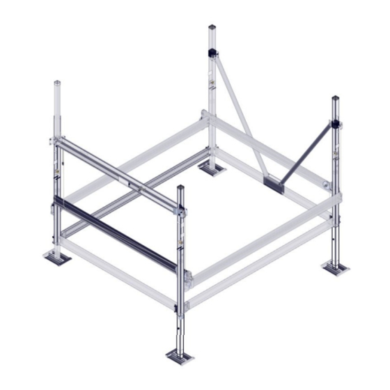
Frame beams are fastened to the corner posts using
the pre-attached lower clamps. See clamp layout top
view in Fig. 2C. Insert frame beam spacers into ends
of all four frame beams before assembly as shown in
Fig. 2D.
For ease of assembly, attach the 118" front and rear
frame beams first. Lay the rear corner posts down and
fasten to the frame beam using (4) 1/ 2" x 4" bolts, (8)
flat washers and (4) nylock nuts. The front frame beam
is attached the same as the rear but use (2) 1/ 2" x 5"
bolts on the bottom holes. Do not tighten the nuts on
the 5" bolts at this time. See Fig 2B and 2C.
The 108" side frame beams are attached using
(4) 1/ 2" x 4" bolts, (8) flat washers and (4) aluminum
nylock nuts on each beam. See fig. 2C.
To help keep the frame square while assembling,
gradually tighten each bolt a little at a time, and
alternate between each side of the clamp. Torque
all clamp bolts to 100 ft/ lbs.
Fig. 2A
rear frame beam
front frame beam
Fig. 2C
Clamp Layout
Lifting corner
1/ 2 x 4" bolt, nut and
washers installed from inside
of lift. Torque to 100 ft/ lbs.
1/ 2 x 5" bolt, nut & washers
installed from outside of lift.
Do not tighten at this time
1"
1/ 2 x 4" bolt, nut and
washers. Torque to 100 ft/ lbs.
SHEET 6 OF 12
Fig. 2D
Spacer Placement
Fig. 2B
Fig. 2A
Fig. 2B
Fig. 2D
1/ 2 x 5" bolt
