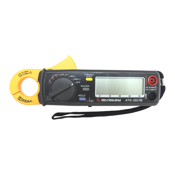
Aktakom ATK-2021B Manuel de l'utilisateur - Page 12
Parcourez en ligne ou téléchargez le pdf Manuel de l'utilisateur pour {nom_de_la_catégorie} Aktakom ATK-2021B. Aktakom ATK-2021B 17 pages. Clamp meter

3.5. Resistance Measurement
3.5.1. Set the rotary switch at Ω .
3.5.2. Insert the test leads into the input jack.
3.5.3. Connect the test prods of the test leads to the two ends of the resistor or
circuit to be measured.
3.5.4. Read the measured value from the LCD display.
3.6. Continuity Test
3.6.1. Turn the rotary switch to Ω position and move the sliding switch to AC
position.
3.6.2. Insert the test leads into the input jack.
3.6.3. Connect the test probes of the test leads to the two ends of the resistor or
circuit to be measured.
3.6.4. Read the measured value from the LCD display.
3.6.5. If the resistance is lower than 10 Ω, a beeping sound shall be heard.
3.7. Frequency (Hz) Measurement
3.7.1. Set the rotary switch at Hz.
3.7.2. Insert the test leads into the input jack.
3.7.3. Connect the test prods of the test leads in PARALLEL to the signal or
circuit to be measured.
3.7.4. Read the measured value from the LCD display.
3.8. Duty Measurement
3.8.1. Set the rotary switch at Duty.
3.8.2. Insert the test leads into the input jack.
3.8.3. Connect the test prods of the test leads in PARALLEL to the signal or
circuit to be measured.
3.8.4. Read the measured value from the LCD display.
3.9. Diode Test
3.9.1. Set the rotary switch at diode.
3.9.2. Insert the test leads into the input jack.
3.9.3. Connect the test prods of the test leads to the two ends of a diode.
3.9.4. Read the diode voltage from LCD.
10
www.tmatlantic.com
